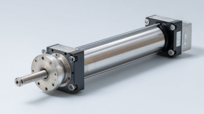
Why Choose a Reaction Torque Cell for Your Application?
Choosing a Reaction Torque Cell makes sense when a test fixture must measure torque without rotating the sensor itself. The cell reacts against a fixed structure, making it useful for motor tests, gearbox checks, and tightening-tool verification. Picture a motor bolted to a bench: its housing pushes against the sensor as the shaft turns. That reaction force becomes a torque reading. Small errors matter.
The right model depends on more than peak torque. Engineers should check the working range, overload capacity, mounting stiffness, expected side loads, signal output, and calibration requirements. A cell sized too high may produce less useful resolution at low torque; one sized too low may be damaged by a brief overload. Cable routing and fixture alignment also deserve attention. They are easy to overlook. Lord Kelvin, a leading measurement scientist, captured the broader principle: “When you can measure what you are speaking about, and express it in numbers, you know something about it.” His words concern measurement generally, not reaction torque cells specifically. Still, they point to a practical goal: readings should be traceable, repeatable, and meaningful in the real test setup.
A Reaction Torque Cell is not automatically the best choice for every application. Rotating systems may call for a different sensor arrangement, while an unsuitable fixture can distort readings. Review the installation, operating cycle, and calibration plan before choosing a model. That extra scrutiny may feel slow. It is often worthwhile.
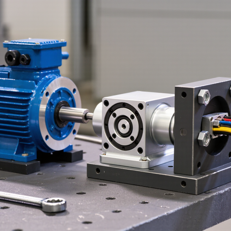
What a Reaction Torque Cell Measures
A reaction torque cell measures the twisting force applied to a stationary or restrained component. When a motor turns against a fixed mount, its housing pushes back with an equal reaction torque. The cell detects this through a small deformation in its sensing element. Strain gauges convert that deformation into an electrical signal, which calibrated equipment reports in units such as newton-metres. Direction matters. Clockwise and counterclockwise readings can reveal changing loads, control behavior, or unexpected friction. The cell measures torque at its mounting point, not every force inside the machine.
This measurement is useful when testing motors, gear assemblies, fasteners, or laboratory fixtures. A technician might secure a motor, apply a controlled load, and watch the torque rise on a display. Reliable readings depend on alignment, a rigid mount, and calibration suited to the expected range. Side loads, vibration, temperature shifts, and loose fasteners can distort results. Not every setup is tidy. Installation details are easy to underestimate; even an accurate sensor can produce misleading data if the fixture flexes. A reaction cell also is not a direct shaft sensor for every freely rotating setup.
How a Reaction Torque Cell Detects Applied Torque
A reaction torque cell measures torque by resisting rotation, rather than spinning with the shaft. Bolt a fixture or motor housing to its body, then apply torque through the connected shaft. The cell’s elastic sensing section twists by a tiny amount. Strain gauges bonded to that section stretch or compress, changing their electrical resistance. A Wheatstone bridge converts those changes into a voltage signal. Small movement. A calibrated readout translates the signal into torque.
The signal depends on more than the applied load. Mounting stiffness, alignment, temperature, and vibration can all affect readings. For example, a slightly flexible test bracket may absorb some motion and distort the result. This detail is easy to miss. ISO 6789-1:2017 gives many manual torque tools a permissible indication deviation of ±4%; some tool classes allow ±6%. These are tool limits, not guaranteed reaction-cell accuracy, but they show why calibration and uncertainty matter. ISO 6789-2:2017 also sets requirements for calibration and measurement uncertainty. A traceable calibration across the intended operating range helps confirm that the cell’s output matches applied torque. Check mounting conditions too. Real test rigs are rarely perfectly rigid.
Where Reaction Torque Cells Are Used
Reaction torque cells are used when a machine’s housing stays fixed while its torque is measured. They are common on test benches for electric motors, gearboxes, pumps, and compressors. A cell mounted between the test unit and its support measures the twisting force transferred into the fixture. This helps engineers compare performance under different loads, speeds, and temperatures. They also support assembly checks, such as verifying the torque reaction from powered fastening tools. Real loads vary.
The need for dependable drivetrain testing is substantial. OICA reported that the world produced about 93.5 million motor vehicles in 2023. The International Energy Agency reported nearly 14 million electric car sales that year, around 18% of global car sales. These figures describe vehicle production and sales, not torque-cell demand; they do show why repeatable motor and transmission testing matters. In practice, engineers must match a cell’s capacity to expected peak torque, then check alignment and mounting stiffness. A fixture that looks rigid may still flex, adding measurement error. Cable routing and temperature can matter, too. Small setup details are easy to overlook.
Why Choose a Reaction Torque Cell for Your Application? — Where Reaction Torque Cells Are Used
| Application |
What It Measures |
Typical Installation |
Why a Reaction Torque Cell Fits |
Practical Consideration |
| Electric motor testing |
Torque reacted by the motor housing or a restrained test fixture during operation. |
The motor or test fixture is mounted so its reaction torque is transferred through the cell to a stationary frame. |
It measures torque without placing a rotating sensor in the motor shaft. |
Account for the motor mount, cables, and other connections that could create unintended mechanical load paths. |
| Gearbox and transmission testing |
Reaction torque at a restrained gearbox housing or test-fixture support. |
The housing or fixture is connected to the cell, while the output shaft is coupled to the test equipment. |
It can measure housing reaction torque in a stationary support structure. |
Fixture alignment and stiffness affect how accurately the applied reaction is transferred to the sensing element. |
| Torque wrench calibration |
Applied torque from a hand-operated or powered torque tool. |
The tool is applied to a calibration fixture that transfers its torque to the cell. |
A stationary setup can measure applied torque without a rotating shaft sensor. |
Use a suitable fixture and apply force in the intended direction; the cell must be selected for the required torque and loading conditions. |
| Powered fastening tools |
Reaction torque produced as a nutrunner or other fastening tool tightens a fastener. |
The tool or a dedicated reaction arm is supported through the cell. |
It can capture torque at the tool’s reaction point in a controlled test setup. |
Impact, vibration, and brief torque peaks may require appropriate sensor capacity and data-acquisition settings. |
| Pumps, fans, and other driven equipment |
Torque reacted by a restrained drive assembly or its test support. |
A stationary housing or test frame is connected to the cell while the drive shaft operates. |
It is useful when the reaction load can be measured through a fixed support rather than a rotating shaft. |
Ensure the measured support carries the intended torque; incidental contact or parallel supports can bypass the cell. |
| Stirred vessels and mixers |
Drive reaction torque transferred to a stationary mounting structure. |
The mixer drive or a defined support point is instrumented in a test arrangement. |
It can provide a way to measure torque reaction while the vessel or test fixture remains stationary. |
Consider changing loads, vibration, and the mechanical effects of the mixer’s mounting arrangement. |
Selection note: A reaction torque cell measures torque through the force it resists at a stationary mounting point. Confirm the required torque capacity, direction of loading, mounting geometry, and operating conditions for the specific application.
How to Select a Cell for an Application
Why Choose a Reaction Torque Cell for Your Application?
How to Select a Cell for an Application
Start with the torque your setup will actually produce. Include steady operating load, startup peaks, and any sudden reversals. A cell rated too close to the expected peak may be damaged; one rated far too high can make small changes harder to resolve. Check the manufacturer’s specifications for overload limits and measurement accuracy. Leave a sensible margin, not a guess.
Look at the mechanics around the sensor. A reaction torque cell needs a secure mounting point, and misalignment or side loads can distort readings. Picture the test bench: a motor housing fixed to a bracket, cables routed clear, and fasteners tightened evenly. Measure the available space before choosing a body size or mounting pattern. Small details matter.
Then match the signal output to your data-acquisition equipment. Confirm connector type, supply requirements, sampling rate, and whether you need clockwise and counterclockwise readings. Temperature, vibration, and repeated loading may also affect performance. For rotating machinery, verify that a reaction-style measurement suits the setup; some tests need a rotating torque transducer instead. It is easy to focus on capacity and overlook this distinction. I would recheck the installation assumptions with a real test plan, because a tidy spreadsheet cannot reveal every awkward bracket or cable path.
Which Installation and Calibration Factors Affect Performance
A reaction torque cell can deliver repeatable readings only when its mounting reproduces real operating conditions. Keep the cell’s axis aligned with the applied torque, and use a stiff, flat mounting plate. A soft gasket or uneven bolt tightening can twist the body and add side loading. Route cables away from moving parts; cable tension can disturb small readings. Check the unloaded zero after installation, then apply a gradual load and watch for drift. Small details matter.
Calibration should match the working direction, range, and temperature as closely as practical. EURAMET Calibration Guide No. 14, Guidelines on the Calibration of Static Torque Measuring Devices (2011), describes procedures using multiple torque levels and repeated measurement series. Its example sequence uses five torque steps and three series, helping reveal nonlinearity and repeatability rather than a single-point error. Record mounting orientation, preload, temperature, and zero return alongside the readings. A room-temperature result may not predict performance on a hot production line. That limitation is easy to overlook. Recheck calibration after overloads, fixture changes, or unexplained zero shifts; even a careful setup deserves another look.

 sales@loadcellsensor.com