sales@loadcellsensor.com

How to Choose the Right Hollow Load Cell?
Choosing the right Hollow Load Cell requires more than matching a force rating to a project sketch. The sensor must fit the mechanical structure, loading direction, installation space, and measurement environment. A compact ring-shaped design may look ideal, yet a small mounting error can introduce unwanted side forces. Small details matter.
Start by defining the expected load range, including shock loads and repeated cycles. Select a capacity that protects the sensor without sacrificing measurement resolution. Review accuracy, repeatability, hysteresis, creep, and temperature compensation in the manufacturer’s datasheet. These figures affect real readings, especially when the load changes slowly or the surrounding temperature shifts. Fit changes everything.
The mounting method deserves equal attention. Check the inner and outer diameters, bolt pattern, contact surfaces, cable direction, and available clearance. A Hollow Load Cell should receive a centered, evenly distributed force. Dirt, uneven plates, or tilted hardware can distort results before the signal reaches the amplifier. In practical testing, installation errors often appear more influential than small differences between sensor models.
Consider the output type, excitation requirements, protection rating, overload limit, and calibration documentation. A traceable calibration certificate supports reliable decisions and easier maintenance. However, no specification sheet can predict every field condition. That is where careful trials matter. Test the sensor with representative fixtures, temperatures, and load cycles before final approval. Do not guess.
This guide explains how to compare Hollow Load Cell options with engineering judgment. It also highlights common selection mistakes, because even experienced teams can overlook clearance, cable protection, or long-term drift. The best choice is not always the strongest sensor. It is the sensor that delivers stable, verifiable measurements within the complete system.
Understanding the Structure and Operating Principle of Hollow Load Cells
How to Choose the Right Hollow Load Cell?
Understanding the Structure and Operating Principle of Hollow Load Cells
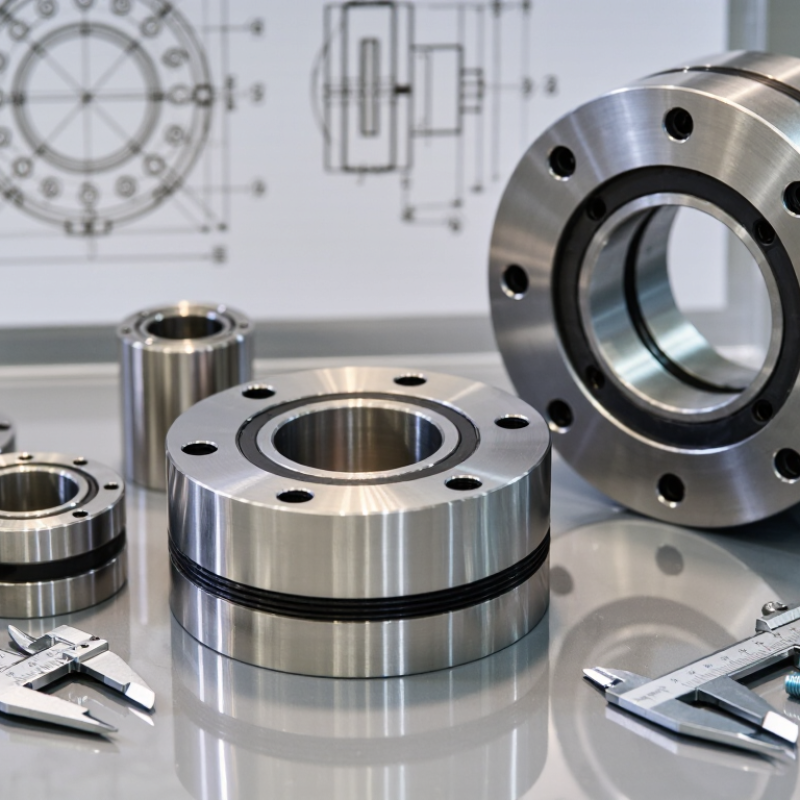
A hollow load cell usually has a ring-shaped elastic body with a central bore. A bolt, rod, or shaft can pass through this opening. The applied force travels through the outer ring and changes its shape slightly. Strain gauges bonded to the elastic body detect this deformation. Their Wheatstone bridge circuit converts the change into a small electrical signal.
The load path matters greatly. Compression models measure force pressing through the ring, while tension-capable designs require suitable mounting hardware. During installation, I check that both contact surfaces are flat, clean, and aligned. Even a slight side load can distort readings. It happens more often than expected. The central opening must also match the bolt or shaft without creating unwanted contact.
Choosing the right model requires more than checking rated capacity. Consider the required accuracy, bore diameter, installation space, excitation voltage, and operating temperature. Sealed construction helps in dusty or damp equipment, but sealing does not replace proper maintenance. In field testing, I compare the sensor output with a certified reference load. I also inspect cable movement and mounting torque. My early selections sometimes focused too heavily on capacity. That approach missed stiffness, alignment, and repeatability. A careful review of the entire force path provides a more dependable choice.
Identifying the Required Load, Accuracy, and Measurement Conditions
Choosing the right hollow load cell starts with the force it must measure. Do not size it only from the machine’s normal operating load. Record the highest expected force, including startup shocks, uneven loading, and accidental overloads. A 10 kN application may briefly reach 14 kN. That difference matters. Select a capacity that protects the sensor without sacrificing useful resolution. An oversized cell can produce stable readings, but small force changes may become difficult to detect.
Accuracy requires more than a percentage in a data sheet. Check whether the stated accuracy includes repeatability, hysteresis, creep, and temperature effects. For a press operating near a warm motor, temperature drift may influence readings throughout a long shift. Ask how the cell was calibrated, under which mounting conditions, and with what measurement equipment. In field work, alignment is often imperfect. Even slight side loads can distort compression measurements. Use a rigid, level contact surface and verify the load path before installation.
The environment also shapes the choice. Dust, moisture, vibration, cleaning chemicals, and limited installation space each demand practical checks. Confirm the protection level, cable routing, operating temperature, and signal compatibility with the readout system. In practical installations, careful calculations can fail because a cable is pulled during maintenance. That detail is easy to miss. Test the complete assembly under realistic loads, not just the sensor alone. If the application changes later, review the original assumptions honestly.
| Selection Criterion | What to Determine | Typical Engineering Data | Selection Guidance |
|---|---|---|---|
| Rated Load | The maximum continuous force that the load cell is expected to measure. | Common ranges include 5 kN 10 kN 20 kN 50 kN 100 kN and higher. | Choose a rated load above the maximum working load, while avoiding excessive oversizing that can reduce usable resolution. Include the mass of fixtures and any preload in the calculation. |
| Load Direction | Whether the force is purely tensile, compressive, or alternates between both directions. | Many hollow load cells are designed primarily for axial compression; some versions are specified for tension and compression. | Use a compression-only design for stable compressive loading. Select a bidirectional model only when reverse loading is permitted in its specifications. |
| Required Accuracy | The acceptable measurement error over the operating load range. | Typical strain-gauge load cells offer combined-error performance from approximately 0.03% to 0.10% of full scale, depending on design and calibration. | For general force monitoring, 0.05% to 0.10% of full scale is often adequate. Choose approximately 0.03% or better when calibration, testing, or process-control requirements are more demanding. |
| Resolution | The smallest force change that the complete measurement system must detect. | Resolution depends on the load-cell output, signal conditioner, amplifier, analog-to-digital converter, noise, and mechanical stability. | Do not determine resolution from the load cell alone. A high-capacity sensor may not provide adequate low-load resolution if the required force is only a small percentage of its full scale. |
| Output Signal | The electrical interface required by the indicator, PLC, data acquisition unit, or controller. | Common strain-gauge outputs are approximately 1 to 3 mV/V at rated load. A separate instrumentation amplifier or transmitter is normally required. | Verify compatibility with the excitation voltage, input range, wiring configuration, and signal-conditioning equipment. Keep low-level signal wiring away from motor and power cables. |
| Excitation Voltage | The regulated supply voltage provided to the Wheatstone bridge. | Typical excitation is 5 VDC or 10 VDC; the allowable range must be confirmed for the selected sensor. | Use a clean, stable excitation source. Excessive excitation can increase self-heating and introduce thermal drift, while unstable excitation can affect measurement accuracy. |
| Overload Protection | The maximum temporary load the sensor can withstand without permanent damage. | Many load cells specify safe overload near 120% to 150% of rated capacity and ultimate overload near 200% to 300%, but values vary by construction. | Select protection based on credible shock and overload conditions. Mechanical stops, load limiting, and proper alignment are still required; overload ratings are not a substitute for system protection. |
| Installation Geometry | The available outer diameter, inner bore, height, mounting method, and load-introduction surfaces. | Hollow designs are available with different through-hole diameters and external profiles for bolts, tie rods, columns, or force-introduction fixtures. | Confirm that the bore accommodates the shaft or fastener without contact. The loading surfaces should be parallel, centered, clean, and sufficiently rigid to prevent bending loads. |
| Eccentric and Side Loads | The amount of off-center loading, lateral force, or bending moment present during operation. | Load cells are primarily intended for axial force. Eccentricity and side loading can create output errors and may exceed allowable mechanical limits. | Use self-aligning hardware, spherical washers, guided fixtures, or separate mechanical supports where appropriate. Keep the resultant force on the intended load axis. |
| Operating Temperature | The ambient and sensor temperature range during measurement, including thermal cycling. | A common compensated range is approximately −10°C to +40°C, while many industrial designs operate over wider ranges such as −20°C to +80°C. | Check both compensated and operating temperature ranges. For temperature-sensitive measurements, allow thermal stabilization and consider temperature compensation in the signal chain. |
| Environmental Protection | Exposure to dust, water, oil, chemicals, washdown, humidity, or condensation. | Sealed load cells may be available with protection levels such as IP65, IP67, or IP68, depending on construction and cable sealing. | Choose the protection level according to the actual environment. IP ratings describe ingress protection under defined test conditions and do not guarantee resistance to every chemical or cleaning process. |
| Creep and Stability | The output change while a constant load is maintained over time. | Creep is commonly specified as a percentage of rated output over a defined period, often 30 minutes, at a stated load and temperature. | Use a low-creep design for long-duration holding, weighing, clamping, or calibration applications. Keep the mounting structure stable and minimize temperature changes during the test. |
| Fatigue Life | The number of loading cycles and the load profile expected over the service life. | Fatigue performance depends on stress level, mean load, cycle frequency, alignment, and overload history; manufacturers may specify millions of cycles under defined conditions. | For cyclic applications, compare the expected duty cycle with the stated fatigue rating. Avoid operating continuously near rated capacity if long service life is required. |
| Calibration and Verification | How the measurement will be checked, adjusted, and documented. | Calibration should cover the intended force range and use traceable reference equipment appropriate to the required uncertainty. | Plan for zero checks, repeatability checks, and periodic calibration. The complete installed system should be verified because fixtures, cabling, temperature, and alignment affect the final result. |
Selecting the Suitable Hollow Load Cell Design and Material
A hollow load cell must match the force path, not just the advertised capacity. Measure the bolt, shaft, and contact-plate dimensions before choosing the bore diameter. A narrow opening may restrict installation. An oversized opening can reduce support stability.
In compression applications, a through-hole design often fits bolt preload monitoring and structural testing. For tension measurement, verify whether the sensor supports a suitable loading fixture. The force should remain centered. Misalignment creates uneven stress and unreliable readings.
Material selection depends on the working environment. Stainless steel suits washdown areas, humidity, and mild chemical exposure. Alloy steel can provide high strength in controlled indoor systems. However, coating damage may expose the metal. Think beyond the datasheet. Check sealing, cable protection, temperature range, and resistance to repeated loading. A sealed construction helps protect internal components from dust and moisture. It does not make careless installation harmless.
In field setups, technicians often overlook surface flatness. A rough mounting face can introduce bending. Use a calibrated torque wrench when tightening fasteners, and record the installation torque. Leave enough clearance for thermal expansion. Sensors with temperature compensation usually improve stability, but compensation is not perfect. Test the assembled system at low, medium, and high loads. One detail still deserves reflection: the strongest material is not always the best choice. The correct design balances accuracy, durability, installation space, and maintenance access.
Checking Installation Space, Mounting Method, and Load Alignment
Choosing a hollow load cell starts with the space around its central bore, not the catalog capacity. Measure the bore, outer diameter, height, cable exit, and tool clearance. Leave room for washers and preload hardware. A 2 mm gap can disappear after thermal expansion or frame movement. Check the force path at full stroke, not only at rest. The cell should sit on a flat, hardened surface. Burrs and paint create uneven contact. They can produce false bending signals. Check the bore twice.
A practical installation check uses a dummy ring or machined spacer before the sensor arrives. It reveals blocked access and short threads early. A neat drawing can still mislead. I have seen “perfect” layouts fail because a wrench could not reach the retaining nut. Threaded rods need controlled preload and matched washers. Compression stacks need parallel faces and a clear load axis. Avoid side loads from guide rails, eccentric pistons, or cable tension. Record seating torque, contact surfaces, and alignment readings during commissioning. Repeat the test after several load cycles.
NIST Technical Note 1297 states that a coverage factor of k=2 generally represents about 95% coverage when assumptions hold. Installation effects can increase that uncertainty. ISO 376:2011 assesses repeatability, reproducibility, creep, zero return, and interpolation error. Use these checks during calibration. Do not guess. Question the result when mounting conditions change.
Comparing Environmental Protection, Calibration, and Maintenance Needs
How to Choose the Right Hollow Load Cell?
Environmental protection should match the installation, not just the product sheet. IEC 60529 defines IP67 as protection against temporary immersion up to one metre. IP68 requires a deeper, manufacturer-specified immersion condition. Neither rating confirms resistance to detergents, salt, dust, or thermal shock. In food, chemical, and outdoor systems, inspect cable seals, mounting surfaces, and drainage paths. Small gaps can collect water and cause unstable readings.
Calibration needs equal attention. OIML R 60 classifies load cells by accuracy, repeatability, and temperature effects. A higher accuracy class may be wasted when the structure flexes or vibration dominates. NIST Technical Note 1297 recommends reporting measurement uncertainty with a coverage factor of k=2, commonly representing about 95% confidence. Record zero balance, span, temperature, and applied test loads. Three points are better than one. More points are safer.
Maintenance is often underestimated. Clean around the hollow bore, but avoid forcing liquid through seals. Check bolt torque and cable strain after installation, then compare readings against the previous calibration record. Real plants are messier. A six-month interval may work in a stable room, yet fail beside washdown equipment. ISO 10012 supports measurement-management systems, but it cannot choose the interval for you. That decision should follow drift history, load cycles, contamination, and the cost of an incorrect reading. One assumption may need revision.
How to Choose the Right Hollow Load Cell?
Comparing environmental protection, calibration stability, and maintenance needs
Higher IP ratings provide better protection against dust and water ingress. A longer calibration interval can reduce scheduled downtime, while fewer annual maintenance hours generally indicate a lower service burden. The values shown are representative engineering reference figures; actual performance depends on installation, cleaning conditions, loading cycles, and the manufacturer’s specifications.
Related Posts
-
China Best Donut Load Cell Supplier for Global Buyers
-

Top Strategies for Selecting the Best 5kg Load Cell for Your Business Needs
-
2025 How to Choose the Right Hollow Load Cell for Accurate Measurements
-

Best Tension Load Cell for Accurate Weight Measurement?
-

Top 10 Benefits of Using 3D Load Cells in Modern Applications
-
What is a Load Cell Sensor and How Does it Work?