Leave Your Message
banner_21

What Is a Multi Axis Load Cell and How Does It Work?

A Multi-Axis Load Cell measures forces and moments acting in several directions at the same time. Unlike a single-axis sensor, it can detect X, Y, and Z forces, plus rotational moments around those axes. This makes it valuable in robotic grippers, vehicle testing, medical devices, aerospace structures, and industrial assembly equipment.

Dr. Ron Lumia, an experienced robotics and force-sensing engineer, offers a useful principle: “The sensor is part of the system, not the whole system.” That idea matters here. A Multi-Axis Load Cell does not simply produce one number. Its internal strain gauges deform slightly when a load reaches the sensing body. Wheatstone bridge circuits convert those tiny changes into electrical signals. The electronics then separate the combined signals through calibration matrices.

The process sounds clean. Real systems are less tidy.

A vertical force may create a small sideways signal. This effect is called cross-talk. Temperature, cable movement, uneven mounting, and nearby vibration can also influence the output. Proper installation is essential. The mounting surface should be rigid, flat, and free from unexpected stresses. Calibration should match the intended load range and operating environment.

A careful engineer checks the data, not just the datasheet. They compare known weights, inspect zero drift, and question unusual readings. That last step is often overlooked. Accuracy is not created by the sensor alone. It depends on design, calibration, installation, maintenance, and interpretation. Understanding how each part works helps users choose the right Multi-Axis Load Cell and avoid confident but incomplete conclusions.
What Is a Multi Axis Load Cell and How Does It Work?

Definition and Purpose of a Multi-Axis Load Cell

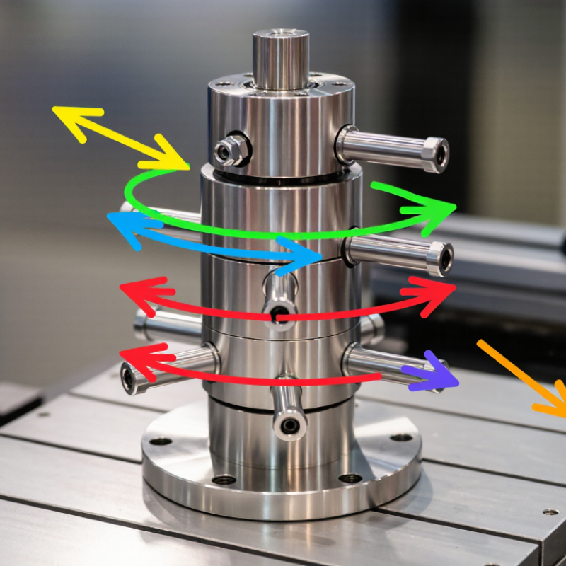
A multi-axis load cell is a precision sensor that measures force and torque in several directions at once. A six-axis model typically records three forces: Fx, Fy, and Fz. It also measures three moments: Mx, My, and Mz. Its purpose is simple but demanding: it shows how a load acts, not merely how heavy it is.

Inside the sensor, carefully arranged strain gauges detect tiny elastic changes in a metal structure. Calibration software then converts these changes into usable force and torque values. Engineers use this information in robotic assembly, medical testing, material research, and structural monitoring. The International Federation of Robotics reported 541,302 industrial robot installations worldwide in 2023. That figure underlines the growing need for reliable contact-force measurement in automated systems.

Accuracy depends on more than the sensor’s advertised capacity. ISO 376 emphasizes traceable calibration, repeatability, and uncertainty evaluation for force-measuring instruments. Temperature, mounting stress, cable movement, and cross-talk can still distort readings. Cross-talk means force on one axis affects another output. It is easy to overlook. In practical testing, a rigid fixture and regular calibration often matter as much as resolution. Even experienced users may misread torque when the load center shifts. A multi-axis load cell works best when its mechanical setup, software model, and calibration data are treated as one measurement system.

Core Components and Measurement Axes

A multi axis load cell measures force from more than one direction at the same time. Its core structure usually includes an elastic metal body, bonded strain gauges, wiring, and protective housing. When force reaches the sensing body, the metal deforms by a very small amount. The strain gauges detect this change and convert it into electrical signals through a Wheatstone bridge circuit. Signal conditioning then amplifies and separates the output for accurate analysis. The housing protects sensitive parts from dust, vibration, and accidental contact.

Measurement axes define how the load cell interprets force. The X and Y axes normally capture horizontal forces, while the Z axis measures vertical force. Some designs also measure moments around these axes, often called roll, pitch, and yaw. This combination helps engineers study gripping, pressing, robotic movement, and material testing. However, the axes are not perfectly independent. A force applied on Z may create a small X or Y response, known as cross-talk. Calibration reduces this error, but it does not erase every practical limitation. Mounting matters too. Uneven bolts, tilted surfaces, or cable tension can distort readings. The ideal diagram is cleaner than the workshop. Careful installation and repeated verification remain essential.

How Forces and Torques Are Detected

What Is a Multi Axis Load Cell and How Does It Work?

How Forces and Torques Are Detected

A multi-axis load cell measures forces from several directions at the same time. It commonly detects three linear forces: X, Y, and Z. It may also measure three torques around those axes. The sensing body contains machined flexures that deform slightly under load. Strain gauges bonded to these areas respond to that deformation. Their electrical resistance changes. Very small changes.

These gauges usually form Wheatstone bridge circuits. The bridge converts mechanical strain into a measurable voltage signal. A vertical force may compress one section while stretching another. A sideways force creates a different strain pattern. Torque produces opposing strain changes across the sensing structure. The electronics compare these signals and calculate each force and moment. This separation requires a calibrated measurement matrix.

In practical testing, mounting quality matters as much as sensor design. Uneven bolts, loose fixtures, or cable tension can create false readings. Temperature can shift the output, too. Engineers therefore apply known loads in controlled directions during calibration. They record cross-talk between channels and correct it mathematically. The ideal equations are clean. Real measurements are not. A small error in alignment can affect several axes at once. Checking zero output before every test is simple, but often neglected. Reliable results depend on correct installation, stable sampling, and calibration records that show how the sensor behaved.

What Is a Multi Axis Load Cell and How Does It Work? - How Forces and Torques Are Detected

Measurement Dimension Symbol Physical Quantity Typical Unit How It Is Detected Typical Application
Force along the X-axis Fx Linear force acting from side to side along the sensor's X-axis N, kN Strain in the sensing structure is converted into an electrical signal by strain gauges or another force-sensitive element. Horizontal load measurement, robotic motion control, and friction testing
Force along the Y-axis Fy Linear force acting from side to side along the sensor's Y-axis N, kN Mechanical deformation caused by the Y-direction load changes the measured electrical resistance or sensor output. Multidirectional force monitoring and machine-tool measurement
Force along the Z-axis Fz Axial or vertical force acting along the sensor's Z-axis N, kN Compression or tension in the load-bearing structure produces a calibrated output proportional to the applied force. Press-force measurement, weighing, compression testing, and assembly inspection
Torque about the X-axis Mx Twisting moment around the X-axis, also called roll torque N·m Shear and bending strains distributed around the sensing body indicate the applied rotational moment. Rotary joint testing, aerospace component testing, and robotic wrist monitoring
Torque about the Y-axis My Twisting moment around the Y-axis, also called pitch torque N·m Strain patterns caused by the moment are measured and separated from the other force and torque components through calibration. Gimbal testing, actuator evaluation, and aerodynamic load measurement
Torque about the Z-axis Mz Rotational moment around the Z-axis, also called yaw torque N·m Torsional deformation in the sensing element changes the electrical output of the measurement bridge. Fastener testing, motor torque measurement, and tool-control systems
Common six-axis configuration Fx, Fy, Fz, Mx, My, Mz Three orthogonal forces and three orthogonal torques measured simultaneously N and N·m Multiple sensing regions measure different strain patterns. A calibration matrix mathematically separates the six output channels. Robotic force control, biomechanics, crash testing, and research platforms
Sensing element — The elastic mechanical structure that deforms under load — The structure is designed to deform slightly and predictably while remaining within its elastic range. Any application requiring repeatable force and torque measurement
Strain measurement ε Small mechanical deformation produced by an applied load Microstrain, µε Bonded strain gauges detect changes in resistance related to tensile, compressive, or shear strain. Precision measurement of static, dynamic, and changing loads
Electrical signal conditioning — Amplification and conversion of the low-level sensor signal mV/V, V, digital counts A bridge circuit, instrumentation amplifier, and analog-to-digital converter prepare the signal for data acquisition. Industrial controllers, test systems, and embedded measurement equipment
Cross-talk compensation C Correction for unwanted output caused by loads applied on other axes % of full scale Factory or laboratory calibration determines how each axis responds to all six loads; compensation uses a calibration matrix. High-accuracy robotics, medical research, and precision testing
Calibration relationship Output = C × Load Mathematical conversion from measured electrical signals to force and torque values — The calibration matrix converts raw channel readings into the six-component load vector. Real-time force estimation and traceable measurement systems
Coordinate reference X, Y, Z Defined orientation used to identify force and torque directions — Each output is interpreted according to the sensor's marked or documented axis orientation and sign convention. System integration, robotic programming, and repeatable test setup
Overload protection — Ability to withstand loads above the rated measurement range without permanent damage % of rated capacity Mechanical stops, robust elastic elements, and installation limits help prevent excessive deformation. Industrial equipment exposed to accidental impacts or unexpected loads
Key performance factors — Accuracy, resolution, repeatability, stiffness, bandwidth, and temperature stability Varies by design Performance depends on the mechanical design, sensing technology, electronics, calibration quality, mounting, and environment. Choosing and integrating a multi-axis load cell for a specific measurement task

Signal Processing and Data Interpretation

A multi-axis load cell measures force along several directions, often X, Y, Z, plus torque around those axes. Its strain gauges change resistance when the structure deforms. A conditioning circuit converts these tiny changes into voltage signals. The difficult work begins after measurement.

Signal processing must separate real force from electrical noise, vibration, temperature drift, and channel cross-talk. Each raw channel passes through calibration coefficients, usually as a matrix. This corrects how one force direction influences another. The system then applies filtering, coordinate transformation, and tare compensation. Sampling matters. The Nyquist principle requires sampling above twice the highest meaningful vibration frequency, yet practical systems often need a much higher margin. ISO 376 calibration guidance and NIST Technical Note 1297 both emphasize traceability and uncertainty evaluation. A 2024 MarketsandMarkets force-sensor report estimated the market could grow from about 2.3 billion US dollars in 2023 to roughly 3.8 billion by 2028. Such forecasts vary, so they should not replace calibration evidence.

Tips: Record raw data before filtering. Check zero drift with no applied load. Use a known load in every axis, then test combined loading. Watch the residual error. A perfect-looking waveform can still be wrong. In bench work, I would inspect temperature and mounting stiffness before changing software. That step is easy to skip. It should not be. Calibration files also need version control, because one coefficient change can alter the interpreted force vector.

Multi-Axis Load Cell Signal Processing and Data Interpretation

A multi-axis load cell measures force components along multiple orthogonal axes. The chart shows representative time-domain data after calibration and low-pass filtering, allowing the applied load and signal stability to be interpreted across the X, Y, and Z axes.

Interpretation: The Z-axis carries the dominant compressive load, while the smaller X- and Y-axis values indicate lateral forces. Short-term variations reflect measurement noise, vibration, and changes in the applied load.

Common Applications and Selection Considerations

A multi axis load cell measures force in several directions at once. It commonly detects tension, compression, and shear along three axes. Inside, bonded strain gauges respond to tiny structural deformations. Electronics convert these changes into electrical signals. The result is a force vector, not just one load value. This matters when forces overlap, such as during gripping, pressing, or robotic movement.

Common applications include robotic assembly, medical device testing, aerospace research, vehicle development, and platform weighing. A six-axis model can also measure torque around each axis. Selection should begin with the expected force range, torque range, and loading direction. Check overload capacity carefully. A sensor used near its limit may lose accuracy or suffer permanent damage. Environmental factors also matter, including temperature, moisture, vibration, and available installation space. Calibration quality and signal compatibility deserve equal attention. A highly sensitive sensor is not automatically the best choice.

Tips: Map every expected force and torque before ordering. Allow practical safety margins. Confirm mounting stiffness, cable routing, and sampling speed with the test engineer. Crosstalk can distort results when one load affects another measurement. Many selection errors come from ignoring this detail. No method is flawless. Real testing may reveal unexpected side loads, so review the sensor data after installation and adjust the setup when necessary.