Leave Your Message
banner_21

2026 Best 3-Axis Force Sensor for Your Needs?

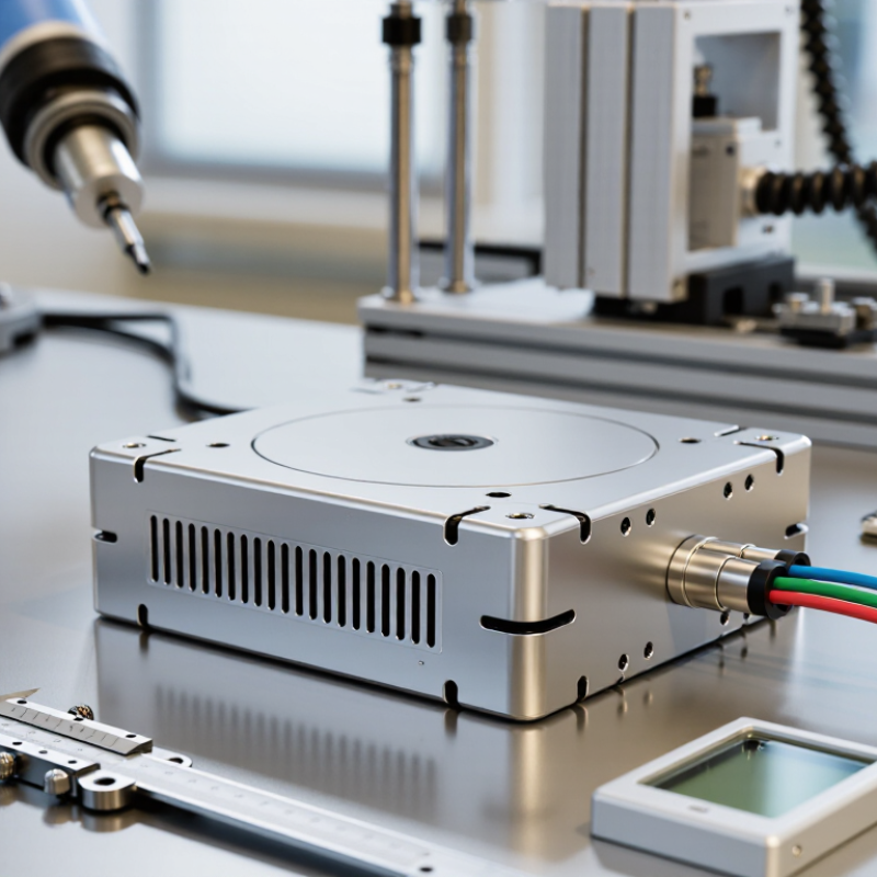
Choosing the right 3-Axis Force Sensor in 2026 requires more than comparing prices or advertised capacity. A reliable sensor must measure force along the X, Y, and Z axes with stable accuracy. It should also match your machine’s speed, mounting space, environmental conditions, and control system.

In practical testing, small errors can become serious problems. A robotic gripper may register different readings when its cable bends. A production fixture may drift after hours of heat exposure. These details matter. Look for clear calibration data, overload protection, repeatability specifications, and compatible signal outputs. An IP-rated housing may be essential near coolant, dust, or cleaning fluids. It is not always essential in a controlled laboratory.

Experience also shows that the highest measurement range is not automatically the best choice. A sensor rated far above the expected load can reduce useful resolution. Meanwhile, an undersized model may suffer damage during sudden impacts. That trade-off deserves careful review.

There is no perfect sensor for every application. Even respected manufacturers may present specifications under different test conditions. Independent verification is valuable. Ask how accuracy was measured, whether temperature compensation was included, and how often recalibration is recommended. Those questions can expose hidden limitations.

This guide compares the leading 3-Axis Force Sensor options for 2026. It focuses on measurable performance, installation practicality, long-term reliability, and real application needs. Some recommendations may change after testing. That is acceptable. Good engineering leaves room for evidence, correction, and improvement.
2026 Best 3-Axis Force Sensor for Your Needs?

What a 3-Axis Force Sensor Measures

2026 Best 3-Axis Force Sensor for Your Needs?

What a 3-Axis Force Sensor Measures

A 3-axis force sensor measures force along three perpendicular directions, commonly labeled X, Y, and Z. Instead of reporting one combined load, it shows each directional component at the same time. For example, a small probe pressing a surface may record downward force on Z and sideways friction on X. The exact axis orientation depends on how the sensor is mounted.

These measurements help reveal how a part or tool is loaded during contact, handling, or testing. A sensor can detect pushing and pulling, provided its design supports the expected load direction. The three readings can also be combined to estimate total force. That distinction matters. A 3-axis force sensor measures linear force components, not necessarily twisting torque; torque requires suitable sensing and setup. Results also depend on calibration, mounting stiffness, sampling rate, and the sensor’s measurement range. A loose fixture can distort the data. Real setups are rarely perfect, so check readings against a known load when accuracy matters.

Tips: Confirm which physical direction each axis represents before testing. Apply a gentle load in one direction at a time, and watch for unexpected cross-axis readings. Keep the sensor securely mounted, avoid exceeding its rated range, and record the calibration details alongside your data.

How 3-Axis Force Sensors Work

A 3-axis force sensor measures force along the X, Y, and Z directions. Inside, bonded strain gauges deform slightly under load. Their resistance changes, creating voltage differences in a Wheatstone bridge. Electronics then convert these signals into force values, often measured in newtons.

The sensor does not simply “feel” pressure. It separates compression, tension, and sideways loads through carefully arranged sensing elements. A calibration matrix corrects interaction between axes, known as cross-talk. This matters during robotic gripping, insertion, and surface inspection. The International Federation of Robotics reported 541,302 industrial robot installations worldwide in 2023, showing why reliable force feedback is becoming more important in automated equipment.

Choose a sensor by range, overload capacity, resolution, sampling rate, and mounting direction. A small sensor may detect a light contact but fail under sudden impact. A larger model may survive higher loads, yet lose sensitivity. Check calibration certificates and temperature compensation data. Standards-based testing also improves traceability. ISO 9283 provides useful guidance for robot performance evaluation, although it does not replace force-sensor calibration.

Real workshop conditions are less tidy. Cable movement, vibration, and uneven mounting can distort readings. I have found that a perfectly rated sensor can still perform poorly after careless installation. That deserves more attention. Calibration should match the real tool, load direction, and operating temperature.

Key Specifications for Comparing 2026 Models

For a useful 2026 comparison, start with the force range on each axis, not the headline capacity. A sensor rated for large forces may lose useful resolution when measuring light contact. Check resolution, repeatability, and nonlinearity under the same conditions. Numbers need context. Ask whether specifications apply across the full range or only near the center. Cross-axis sensitivity matters when a test applies force at an angle. Even a small unwanted reading can distort results in a precision assembly test.

Next, compare bandwidth, noise, and overload limits against the real test setup. A fast impact measurement needs a higher usable bandwidth than a slow compression test. Look for details on filtering, sampling, and calibration, not just a maximum frequency. Fit matters too. Check mounting dimensions, cable direction, connector type, and temperature compensation before designing a fixture around the sensor. Overload protection should suit likely peaks, while staying clear of the normal operating range. A published accuracy figure can be hard to compare if models use different mounting methods or test conditions. That detail is easy to overlook. Review calibration documentation and confirm how often recalibration is recommended for your workload. When specifications leave gaps, request test conditions and uncertainty data; a tidy comparison table cannot replace them.

Best 3-Axis Force Sensors for Different Applications

The best 3-axis force sensor depends on the task, not the highest advertised range. For robotic assembly, choose low cross-axis interference, fast sampling, and overload protection. The International Federation of Robotics reported 541,302 industrial robots installed worldwide in 2023. That growth increases demand for reliable contact detection during insertion, polishing, and quality inspection. A 10 N sensor may suit delicate fitting, while a 1,000 N model may be necessary for pressing operations.

Small forces matter too. Rehabilitation devices and prosthetic research require accurate measurements across changing loads. The World Health Organization’s Global Report on Assistive Technology estimates that more than 2.5 billion people need assistive products, potentially rising beyond 3.5 billion by 2050. For these applications, prioritize resolution, temperature stability, hygienic surfaces, and simple calibration procedures. Patient comfort also matters. A sensor can be accurate yet unsuitable if its housing feels bulky or rigid.

Test benches need a different balance. Engineers should check rated capacity, fatigue performance, signal noise, and sampling frequency under real mounting conditions. ISO 9283 provides guidance for industrial robot performance testing, but it does not remove the need for application-specific validation. A neat specification sheet can still mislead. I would test cable movement, fixture stiffness, and side loading before approval. No sensor is perfect. Some field failures come from mounting errors rather than poor sensing elements. Calibration records should include temperature, load direction, and repeatability data.

2026 Best 3-Axis Force Sensor for Your Needs?

Compare example force components for different loading directions when planning a three-axis measurement.

Values are calculated ideal, static loads using standard gravity (9.80665 m/s²): 1 kg along Z, 1 kg at 45° from Z toward X, and 2 kg at 30° from Z toward X. They are not sensor specifications. Select a sensor with suitable range on each axis, allowing headroom for peaks and considering mounting, cross-talk, and overload limits.

Installation, Calibration, and Maintenance Essentials

2026 Best 3-Axis Force Sensor for Your Needs?

Installation, Calibration, and Maintenance Essentials

A reliable three-axis force measurement begins with a rigid, flat mounting surface. Clean the contact faces, remove burrs, and tighten fasteners evenly to the specified torque. Small alignment errors can create unwanted side loads. Keep the sensor’s sensing axes aligned with the applied forces, and route cables away from moving parts. Leave a gentle service loop; a taut cable can pull on the sensor and distort readings. Check the load direction before powering the system. It is easy to overlook.

Calibrate the sensor after installation, not only on a workbench. Allow the system to warm up as specified, then record the unloaded zero. Apply traceable reference loads separately along each axis, using several points across the expected working range. Check combined-axis loading if your application uses it. Compare readings with the reference values and document temperature, mounting details, and any deviations. A neat calibration sheet is useful, but it cannot correct a loose fixture.

Maintenance should be simple and regular. Inspect fasteners, connectors, cable jackets, and the mounting surface for wear or contamination. Recheck zero after a collision, overload, or major setup change. Trends matter: a gradual shift may signal mounting movement or sensor damage. Do not assume every strange reading is a sensor fault; fixtures and cables can be the cause. Record what changed, even when the explanation is not obvious.

2026 Best 3-Axis Force Sensor for Your Needs? — Installation, Calibration, and Maintenance Essentials

Application Need Selection Criteria Installation Essentials Calibration Essentials Maintenance Essentials
Small-part testing and laboratory experiments Choose a measuring range suited to the expected forces on all three axes. Low-capacity sensors can provide useful resolution for small loads, but their usable range and overload limits are model-specific. Mount on a flat, clean surface using the specified fasteners and tightening procedure. Align the sensor axes with the test setup and avoid cable tension or side loading. Use traceable force standards and apply loads along each axis. Check zero, sensitivity, repeatability, and cross-axis response over the intended working range. Keep the sensing area clean and dry. Inspect connectors and mounting hardware, and check for zero drift before critical measurement sessions.
Robotics, grippers, and assembly Consider range, stiffness, size, response time, signal interface, and the effects of expected impacts. Confirm that overload protection is adequate for the robot’s maximum contact forces. Use a rigid, well-aligned interface and secure cables so robot motion does not pull on the sensor. Check that the end-effector does not obstruct the measurement axes. Calibrate in the installed configuration when fixtures or adapters affect load paths. Verify readings with representative forces and moments where the application requires them. Inspect the mounting joint, cable routing, and connectors after impacts or tool changes. Recheck zero and performance if the end-effector configuration changes.
Pressing, insertion, and material testing Select capacity with a safe margin above expected peak loads without sacrificing the resolution needed at lower loads. Review permissible loading direction and overload specifications. Keep the load line centered and apply force through suitable fixtures. Avoid unintended bending, torsion, or uneven contact that can distort readings or damage the sensor. Calibrate using known loads in the actual loading direction. Include loading and unloading checks to identify hysteresis and repeatability issues. Look for loose fixtures, wear, corrosion, and signs of overload. Record unusual readings and remove the sensor from service if damage is suspected.
Multi-axis research and interaction measurement Review measurement ranges for each axis, cross-talk specifications, bandwidth, data acquisition compatibility, and environmental limits. Cross-talk and accuracy values vary by design and test conditions. Set the sensor coordinate system and document its orientation. Use a stable mounting structure and confirm that the data acquisition system uses the correct channel mapping and units. Calibrate each axis separately and perform combined-load checks if simultaneous forces are expected. Use a calibration method appropriate to the required uncertainty. Keep a record of calibration dates, test conditions, and configuration changes. Recalibrate after repairs, overload events, or significant changes to the measurement setup.
Production-line monitoring Prioritize robust construction, repeatable output, appropriate electrical protection, compatible signal conditioning, and a range matched to normal and peak process loads. Follow the specified wiring, shielding, grounding, and environmental protection requirements. Route signal cables away from high-current or noisy power lines where practical. Establish an initial calibration and a documented verification schedule based on process risk, usage, and observed drift. Confirm results with reference equipment. Use routine visual checks and trend monitoring. Clean the installation area safely and inspect seals, cables, connectors, and mounting points at defined intervals.

Selection note: There is no single best 3-axis force sensor for every application. Compare the sensor’s current technical specifications, calibration documentation, operating limits, mounting requirements, and compatibility with your measurement system before purchase. Performance values and maintenance intervals are model- and application-dependent.