Top Load Sensor 50kg for Accurate Industrial Weighing
Accurate industrial weighing begins with a sensor that can handle real pressure, vibration, and repeated loading. A Load Sensor 50kg provides a practical capacity for platform scales, filling machines, conveyor systems, and small hopper applications. Its performance depends on more than the number printed on the datasheet. Installation, alignment, temperature, cable protection, and calibration all influence the final reading.
John S. Bevan, a recognized author on weighing equipment, observed, “The accuracy of a weighing system depends on every part of the system, not only the load cell.” This principle remains highly relevant. A strong Load Sensor 50kg must transfer force evenly, resist overload, and deliver stable electrical signals to the indicator. Stainless steel construction can improve durability in demanding industrial environments, while suitable sealing helps protect internal components from dust and moisture.
Small errors become expensive.
In practical use, an operator may notice a drifting display after several hours near a warm motor. That problem may involve temperature changes, poor mounting, or cable interference, rather than sensor failure. Engineers should inspect the complete weighing assembly before replacing parts. This approach reflects experience, technical judgment, and responsible maintenance.
No sensor is perfect. Even a well-selected Load Sensor 50kg can perform poorly when the platform flexes or the load is off-center. Regular calibration, documented testing, and clear installation procedures support dependable results. Buyers should also verify rated capacity, accuracy class, excitation voltage, environmental protection, and compatibility with the weighing controller. Reliable weighing is not created by one component alone. It is built through careful choices and continuous checking.
Top Load Sensor 50kg: Capacity, Structure, and Industrial Applications
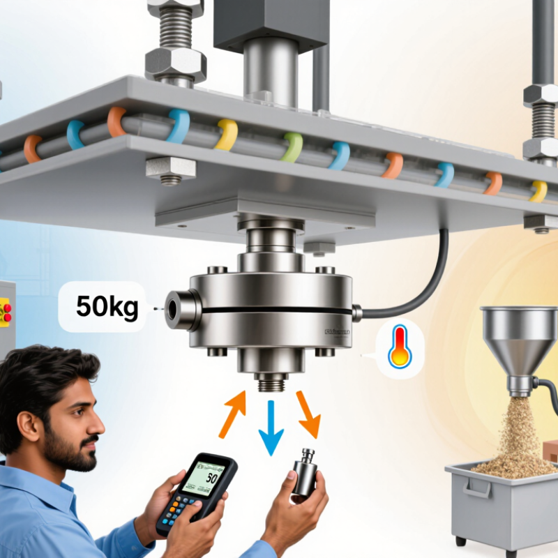
A 50kg top load sensor offers a practical balance between capacity, sensitivity, and compact installation. It measures force through strain gauges fixed to a carefully machined metal element. When weight presses downward, the element bends slightly. The electrical signal then changes in proportion to the applied load.
The structure usually includes a loading platform, sensing element, cable, and protective housing. A stable mounting surface matters. Small alignment errors can create unstable readings or uneven corner response. In working environments, dust, moisture, vibration, and sudden impacts also affect performance. A 50kg rating is not a universal answer. Leave useful headroom above the normal weighing range. This reduces stress and improves long-term reliability. Regular calibration with certified test weights supports traceable results. Still, calibration alone cannot fix poor installation.
Tips:
Keep the platform level and prevent side forces. Protect the cable from sharp bends and moving parts. Test the sensor at several points, not only near zero. For production lines, batching systems, packaging equipment, checkweighers, and small hopper scales, this capacity often fits well. However, dynamic loads may need filtering and faster sampling. I have seen readings drift when operators place containers off-center. That detail is easy to overlook. Temperature changes can also influence output, so serious applications should include compensation and scheduled inspections.
Typical 2–3 mV/V Output and Signal Conversion in 50kg Load Cells
Top Load Sensor 50kg for Accurate Industrial Weighing
A 50kg top load sensor commonly produces 2–3 mV/V at rated capacity. With a 10V excitation supply, this equals only 20–30mV. That signal is small and easily affected by cable resistance, electrical noise, and unstable power. A useful field check is simple: place a certified 50kg test mass and compare the converter’s reading with the expected millivolt change.
Signal conversion usually begins with an instrumentation amplifier. The amplifier raises the low-level bridge output before an analog-to-digital converter samples it. A 24-bit converter is common in precision systems, but its theoretical resolution does not guarantee practical accuracy. Grounding, shielding, temperature drift, and mechanical alignment still matter. Small errors accumulate.
OIML R 60:2017 identifies rated output, repeatability, hysteresis, and combined error as important load-cell performance measures. ISO 376:2011 also emphasizes traceable calibration for force-measuring instruments. These documents support a disciplined setup, not blind reliance on a specification sheet. In practice, I would record zero output before loading, after unloading, and during warm-up. This step is often skipped. That is a weakness. If the sensor delivers 2.4mV/V instead of 3mV/V, the converter must be configured for its actual rated output, not an assumed value. Calibration records should include excitation voltage, ambient temperature, test masses, and conversion settings.
Accuracy Standards: OIML R60 C3–C6 and 0.02%–0.05% Full-Scale Error
A 50kg top load sensor can deliver stable industrial weighing when its accuracy class matches the application. OIML R60 classes C3, C4, C5, and C6 describe increasingly demanding load-cell performance. However, the class alone does not guarantee field accuracy. Installation, temperature, vibration, and cable routing also matter.
For a 50kg capacity sensor, a full-scale error of 0.02% equals about 10 grams. At 0.05%, the possible error reaches approximately 25 grams. These figures require careful interpretation. They may describe rated performance under controlled test conditions, not every operating environment.
A C6 load cell may suit precise batching, while C3 can be practical for general material handling. The correct choice depends on allowable tolerance, weighing speed, and daily loading patterns.
Mount the sensor on a rigid, level surface. Prevent side forces from entering the load path. Calibrate with traceable test weights across several points, not only at maximum capacity. Check zero drift after warm-up and during temperature changes. In practice, a clean installation often improves results more than selecting a higher class. That is easy to underestimate. Even experienced technicians can overlook uneven supports, loose fasteners, or product buildup beneath the platform. Record those observations during commissioning, then verify repeatability before approving the weighing system.
Installation Steps: 5–15 V Excitation, Level Mounting, and Calibration
Top Load Sensor 50kg for Accurate Industrial Weighing
A 50 kg top-load sensor can provide stable measurements when installation details are controlled. Begin by checking the sensor datasheet, wiring diagram, and rated excitation range. Apply a clean 5–15 V DC excitation supply. Confirm the voltage with a calibrated multimeter before connecting the load cell. Incorrect polarity or unstable power can create drifting readings. Keep it clean.
Mount the sensor on a rigid, level surface. Use a precision spirit level across the mounting plate, then tighten fasteners evenly. The loading point should sit directly above the sensor’s active axis. Avoid side forces, twisting, and contact with nearby guards. I have seen small metal chips create uneven support, so inspect the contact surfaces carefully. Do not rush.
Allow the sensor and electronics to stabilize before calibration. Place known reference weights near the center, then repeat the test at several positions. Record zero, span, and repeatability readings. Adjust the indicator only after confirming the mechanical structure is settled. A first calibration is not always perfect; temperature, cable movement, and mounting stress can interfere. Recheck after several loading cycles, and document every adjustment for future technicians.
Top Load Sensor 50 kg: Calibration Performance at 10 V Excitation
The sensor is tested at evenly spaced loads from 0 to 50 kg using a 10 V excitation supply, within the specified 5–15 V excitation range. Level mounting and calibration help keep the measured values close to the applied load.
Environmental Selection: IP65–IP68 Protection for Industrial Weighing Systems
A 50 kg top-load sensor often works near dust, washdown water, and condensation. Environmental protection therefore deserves equal attention to capacity and accuracy. IEC 60529 defines IP65 as dust-tight protection against water jets. IP66 withstands stronger water jets. IP67 supports temporary immersion up to one metre for 30 minutes. IP68 requires continuous immersion under conditions specified by the manufacturer. These ratings are not interchangeable.
The United Nations Environment Programme projects global municipal solid waste to reach 3.8 billion tonnes by 2050, up from 2.3 billion tonnes in 2023. This growth will increase weighing demand in sorting, transfer, and processing facilities. A 50 kg sensor in these areas needs sealed cable entries and corrosion-resistant construction. During installation, keep the connector facing downward. Water often collects at upward-facing joints.
In my field checks, poor mounting creates more errors than rated capacity. An IP68 sensor can still fail when its cable gland is damaged. Calibration also changes after repeated thermal cycling. I would not select IP68 automatically. IP65 may be sufficient indoors, while IP67 or IP68 suits frequent washdown or flood exposure. Review IEC 60529 test conditions, cleaning chemicals, drainage, and service access before approval. Small oversights matter.

 sales@loadcellsensor.com