Leave Your Message
banner_21

7 Tips for Choosing a Force Sensing Load Cell

Choosing a Force Sensing Load Cell is not simply a matter of selecting the highest capacity. The right device must match the real mechanical environment. A laboratory test stand behaves differently from a stamping machine or robotic gripper. Small details matter.

Dr. John P. Bentley, a recognized measurement-systems specialist, has noted, “The accuracy of a measurement depends on the whole measurement system, not one component.” That principle guides this practical introduction. The sensor, mounting surface, cable, amplifier, and calibration method all influence the final reading. Ignore one, and confidence can weaken quickly.

The seven tips ahead examine capacity, overload protection, sensitivity, environmental sealing, temperature effects, mechanical installation, and calibration support. Begin with the actual force range, not an optimistic estimate. A 1,000-newton load cell may seem suitable, yet repeated impacts can damage it. Leave sensible headroom.

Check the datasheet carefully. Look for bridge resistance, excitation voltage, nonlinearity, hysteresis, creep, and operating temperature. These figures reveal how the Force Sensing Load Cell may behave outside a clean laboratory. Mounting also deserves attention. Uneven bolts or side loading can create misleading readings.

There is no perfect choice. Even experienced engineers sometimes focus too heavily on accuracy and overlook installation limits. That is a useful warning. A robust selection process compares performance, compatibility, serviceability, and total cost. It also asks what might fail after six months, not only what works today.
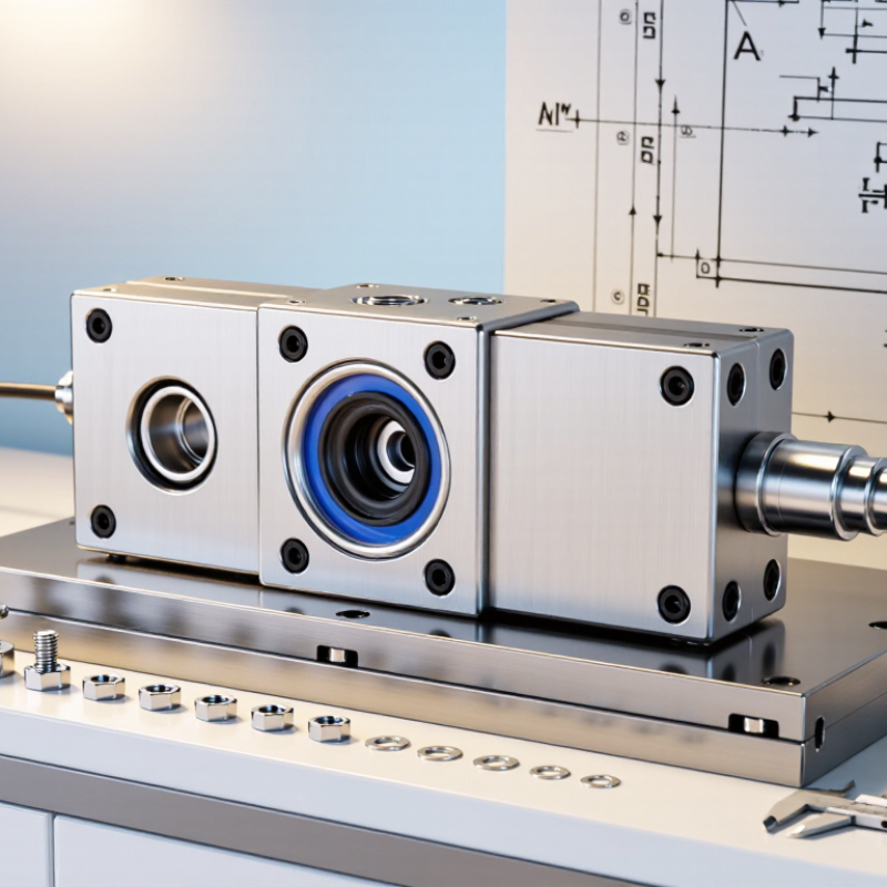
7 Tips for Choosing a Force Sensing Load Cell

Define the Force Measurement Requirements

Defining force measurement requirements is the practical starting point for choosing a force sensing load cell. Before comparing specifications, describe the real load clearly. Record the expected force range, peak force, loading direction, and how often the force changes. A machine pressing 800 newtons steadily needs different performance from a test rig measuring rapid impacts. Do not size the sensor only for the normal load. A sudden 1,200-newton spike may permanently affect accuracy.

Accuracy should match the decision being made. If the process accepts a 5% variation, an extremely precise sensor may add unnecessary cost. For a laboratory measurement, repeatability, hysteresis, creep, and temperature drift deserve closer attention. Define the smallest force that matters, too. A sensor rated for 10,000 newtons may respond poorly to a 20-newton signal. That detail is easy to miss.

Consider the installation environment in specific terms. Will oil, dust, vibration, or washdown exposure occur? Measure the available mounting space and check whether the load will remain centered. Side loads and uneven contact can distort readings, even when the sensor’s advertised capacity looks suitable. Select the electrical output, sampling rate, and cable length around the data system. Calibration should also be planned under the same mounting conditions used in operation. Perfect assumptions rarely survive the first installation. A short trial with known weights can reveal alignment problems before production begins.

Match Load Cell Capacity to the Applied Forces

Choosing a force-sensing load cell begins with the applied force, not the catalog label. Record the normal load, peak load, impact, and loading direction. Include the fixture, tooling, and product weight.

The 2024 World Robotics report recorded 541,302 industrial robot installations worldwide in 2023. Many of these systems depend on controlled force measurement. Capacity errors can therefore affect repeatability, safety, and maintenance costs. A practical starting point is selecting a capacity above the highest expected force, often by 20% to 50%. This margin is only a starting point. Repeated shocks may require more protection.

For example, a process applying 800 newtons continuously, with occasional 1,100-newton peaks, should not use a 1,000-newton cell. A 2,000-newton model may offer safer headroom, but it can reduce resolution at the lower end. That trade-off matters. Check the signal output, resolution, and required accuracy across the working range. ISO 376 calibration guidance also emphasizes traceability and controlled force application during verification. A cell rated for 10 kilonewtons may still perform poorly if side loads or bending are present. I have seen otherwise careful designs fail because the fixture introduced torque. The calculation looked correct. The installation was not. NIST measurement guidance similarly stresses uncertainty evaluation, including influences from alignment, temperature, and repeatability. Test the complete assembly, not only the sensor.

7 Tips for Choosing a Force Sensing Load Cell - Match Load Cell Capacity to the Applied Forces
Tip Selection Dimension Applied-Force Example Suggested Rated Capacity Why It Matters Engineering Check
1 Identify the complete force range Expected force: 0–100 N
Peak force: 100 N
150 N
Approximately 67% of rated capacity at peak load
Choosing a capacity slightly above the maximum working force provides useful measurement headroom without making the sensor unnecessarily insensitive. Include the minimum measurable force, normal operating force, and highest credible peak force.
2 Account for static and dynamic loads Static force: 600 N
Dynamic peak: 1,000 N
1,500 N
Recommended starting point for this example
Acceleration, vibration, impact, and rapid loading can produce forces greater than the nominal static load. Use measured or calculated peak force rather than the average operating force when selecting capacity.
3 Leave practical overload margin Normal peak force: 5 kN
Occasional process variation: up to 5.5 kN
7.5 kN
About 67% of rated capacity at the normal peak
A moderate margin helps accommodate process variation and reduces the likelihood of operating continuously near the rated limit. Confirm the sensor's specified safe overload and ultimate overload ratings; these values are not universal.
4 Match capacity to fatigue loading Repeated cyclic force: 0.2–2.0 kN
Thousands or millions of cycles
3 kN
Illustrative capacity with operating peak near 67%
Repeated operation can cause fatigue even when the force remains below the nominal capacity. Lower stress levels generally support longer sensor life. Review the manufacturer's fatigue-life data for the intended load direction, cycle count, mean load, and load amplitude.
5 Consider load direction and off-axis forces Axial compression: 20 kN
Possible side load: 2 kN
30 kN axial capacity
Use a multi-axis sensor if side-force measurement is required
Many load cells are optimized for one primary loading direction. Bending, torsion, or side loading can affect accuracy or damage the sensing element. Check allowable side load, eccentricity, bending moment, and torsional limits in the technical specification.
6 Protect low-force resolution Measurement range: 0.5–10 N
Required resolution: 0.01 N
15 N
Preferably the smallest capacity that safely handles the peak force
An oversized load cell may reduce the usable signal range and make low-force changes harder to resolve in the complete measurement system. Evaluate rated output, noise, electronics resolution, thermal drift, and calibration uncertainty—not capacity alone.
7 Verify accidental overload protection Normal peak force: 8 kN
Possible accidental event: up to 12 kN
10 kN or higher, only if the specified overload rating safely covers the event Capacity selection must account for foreseeable installation errors, hard stops, dropped loads, and emergency conditions. Compare the accidental force with the documented safe overload limit, install mechanical stops where appropriate, and never rely on rated capacity alone.
General selection rule: Start with the highest credible applied force, including dynamic and off-axis effects, then select the lowest available rated capacity that provides adequate headroom, resolution, fatigue life, and verified overload protection. The numerical capacities shown above are engineering examples; final selection must use the load cell's certified specification and the actual application conditions.

Select the Appropriate Sensing Technology and Structure

Choosing a force sensing load cell starts with the force profile, not the catalog picture. In production tests, I examine whether the load is static, rapidly changing, or repeatedly reversed. Strain-gauge technology suits many static and changing loads. It offers stable readings when temperature compensation and signal conditioning are handled properly. For impact events, piezoelectric sensing can capture fast force changes, but it may drift during long holds. That limitation matters.

The sensing structure should match how force enters the assembly. A compression cell works under a centered vertical load, while an S-beam can measure tension and compression. Bending-beam designs fit lower-capacity platforms and are often easier to integrate. Pancake structures provide a short, rigid load path for higher forces. I always inspect side loads, mounting surfaces, and possible twisting before selecting one. A perfect datasheet rating cannot rescue poor alignment.

Installation details often decide whether laboratory accuracy survives on the factory floor. Use a rigid, flat interface, control bolt torque, and protect the cable from sharp bends. Leave enough overload margin for tool drops, start-up surges, and accidental impacts. Moisture, washdown, dust, and temperature cycling need realistic testing. I once treated mild vibration as harmless, and the signal noise proved otherwise. That was a useful mistake. Verify calibration against a traceable reference, then compare repeatability, hysteresis, creep, and zero return under the actual mounting arrangement.

7 Tips for Choosing a Force Sensing Load Cell: Select the Appropriate Sensing Technology and Structure

Load-cell structure should match the expected force range, installation method, load direction, and available space. The chart shows representative rated-capacity ranges commonly associated with different load-cell structures.

Strain-gauge technology is commonly selected for static and slowly changing forces, while piezoelectric sensing is better suited to dynamic measurements. Capacitive sensing can be useful for low-force applications requiring high sensitivity. Actual capacity, accuracy, overload protection, and bandwidth depend on the mechanical design and operating conditions.

Check Accuracy, Environment, and Installation Conditions

Choosing a force sensing load cell requires more than comparing rated capacity. Accuracy depends on the full measurement chain. NIST Technical Note 1297 explains that expanded uncertainty commonly uses a coverage factor of k=2, representing about 95% confidence. Request this uncertainty value, not only the advertised accuracy figure.

Check seven practical points:

capacity, combined error, temperature drift, creep, humidity protection, mounting, and calibration.

A sensor rated for 1,000 N may perform poorly near its lower measurement range. Select a capacity that covers peak force without sacrificing resolution. Ask for calibration data across your working range.

The environment deserves equal attention. ISO 376:2011 emphasizes controlled calibration conditions, while OIML R 60 classifies load-cell performance under defined requirements. Temperature changes, side loading, vibration, and uneven surfaces can create visible errors.

Keep the force path straight. Use a rigid, clean mounting surface. Remove paint flakes and debris beneath contact points.

Small contamination can matter.

Installation errors are often underestimated. Confirm cable routing, connector sealing, preload, and electrical grounding before testing. Allow thermal stabilization, then record zero output. Repeat loading cycles and compare ascending and descending results.

A stable reading is not automatically an accurate reading. Field conditions rarely match laboratory conditions, and that gap deserves honest review. Calibration should follow actual use, not convenience alone.

Compare Calibration, Durability, and Long-Term Value

Calibration is the first long-term value test. OIML R60:2021 classifies load-cell performance by accuracy classes, maximum permissible errors, and load ranges. Compare certificates carefully. A certificate without uncertainty, traceability, and test conditions tells only part of the story. ISO/IEC 17025:2017 also stresses technically valid methods and measurement traceability. Ask how often recalibration is recommended, not only the initial accuracy. A low-cost cell can become expensive after repeated verification visits.

Durability needs real operating details. Check rated capacity, safe overload, ingress protection, temperature compensation, and cable protection. NIST Handbook 44, 2024, emphasizes repeatable testing and tolerances for weighing equipment. In practice, record ten unloaded readings, then ten readings at a typical working load. Watch for zero drift after vibration or temperature changes. Small changes matter. A 0.05% full-scale error can distort a 20-kilogram process by 10 grams. That may be acceptable in one application and unacceptable in another.

Long-term value is rarely the lowest purchase price. Compare expected service life, recalibration labor, replacement access, downtime, and data stability. One uncomfortable mistake is choosing impressive laboratory accuracy for a harsh production floor. The “best” specification may fail there. Review actual environmental conditions, then leave a sensible margin. Keep the evidence: calibration history, overload events, repair records, and trend data. Those records often reveal value more honestly than a sales sheet.