7 Best Inline Load Cells for Accurate Force Measurement
Choosing the right Inline Load Cell can determine whether a force measurement system delivers dependable data or confusing results. In real applications, small errors matter. A slightly misaligned sensor may display unstable readings, especially during repeated compression, tension, or pulling cycles. The best models combine suitable capacity, low deflection, reliable calibration, and practical installation features.
This guide reviews seven inline load cells for accurate force measurement across testing equipment, automation systems, assembly tools, and laboratory fixtures. Each option deserves attention for different reasons. Some prioritize high precision, while others offer rugged housings, compact dimensions, or easier integration with amplifiers and data acquisition systems. We will examine rated load, accuracy, overload protection, material quality, signal output, and environmental resistance. Details matter here.
Real-world fit matters more than impressive specifications. A sensor rated for 10,000 newtons may be unsuitable if your application needs delicate readings below 100 newtons. Cable routing, mounting threads, temperature changes, and side loading can also influence performance. These factors are easy to overlook. I have found that installation conditions often create more trouble than the load cell itself.
The comparisons remain practical, not absolute. Manufacturer data can vary by testing method, and field results may differ. That is worth remembering. Before choosing, verify calibration certificates, connector compatibility, operating temperature, and required measurement range. The strongest choice is not always the most expensive model. It is the one that matches your equipment, workload, and accuracy expectations without unnecessary complexity.
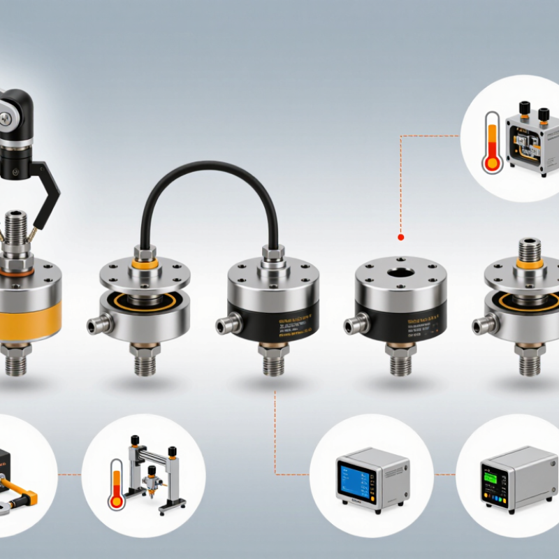
What Inline Load Cells Measure and How They Work
Inline load cells measure force along a single axis, usually through tension, compression, or both. They are installed between connected components, such as a rod, actuator, or test fixture. When force passes through the cell, its internal metal body deforms slightly. The movement is tiny, but measurable.
Most inline load cells use strain gauges arranged in a Wheatstone bridge. As the sensing body stretches or compresses, the gauges change electrical resistance. The bridge converts this change into a small voltage signal. A compatible amplifier or data system then displays force in newtons, pounds, or another selected unit. The measured value depends on calibration, wiring, temperature, and loading direction.
In practical testing, alignment matters more than many users expect. Side loads, loose threads, and uneven contact can distort readings. I have seen a mechanically secure setup produce unstable data because the force path was not centered. That mistake is easy to repeat. Check the rated capacity, confirm zero output, and apply a known reference load when possible. Dynamic measurements also require suitable sampling speed. Temperature drift can remain unnoticed during long tests. A protective overload limit helps, but it does not replace careful installation or regular verification.
Key Specifications for Comparing Inline Load Cells
7 Best Inline Load Cells for Accurate Force Measurement
Key Specifications for Comparing Inline Load Cells
Choosing an inline load cell starts with the measurement task, not the product ranking. Define the expected force range, loading direction, available space, and required sampling speed. A sensor rated far above the working load may reduce useful resolution. A weak sensor may suffer permanent damage during a sudden impact.
Compare rated capacity, combined accuracy, nonlinearity, hysteresis, repeatability, and creep. These values describe different errors, so one impressive accuracy figure can mislead. Check whether specifications are expressed as a percentage of full scale or applied load. That difference matters at low forces. Also examine overload protection, stiffness, natural frequency, and electrical output. High stiffness can improve motion control, but it may increase sensitivity to installation errors.
Temperature compensation deserves close attention. Review the operating range and temperature effect on zero and span. Confirm the connector rating, sealing level, cable flexibility, and mounting thread. In dusty or damp work areas, protection details are practical requirements. Calibration certificates improve traceability, but they cannot correct poor alignment. Use hardened adapters, even contact surfaces, and a verified torque procedure. Small mounting errors can produce surprisingly large readings. I have seen a well-calibrated sensor perform poorly because the fixture twisted under load. Datasheets rarely show every real-world weakness. Compare test conditions carefully, then validate the chosen cell with known reference loads. Perfect measurement is difficult. Reliable measurement is repeatable.
7 Best Inline Load Cells for Accurate Force Measurement
Key Specifications for Comparing Inline Load Cells
This comparison uses representative, brand-neutral specification profiles commonly available for inline force measurement. Rated capacity is shown in kilonewtons, while accuracy and safe overload capacity are plotted on a secondary scale. Lower accuracy values indicate finer measurement capability, whereas higher overload percentages provide more mechanical protection.
Seven Inline Load Cells Selected for Accurate Force Measurement
Seven inline load cells were selected for accurate force measurement across laboratory, automation, and field applications.
The group includes miniature compression, tension-compression, S-beam, pancake, rod-end, button, and high-capacity axial designs.
Each option should match the expected force range, mounting space, loading direction, and environmental conditions.
A sensor operating near its rated capacity usually provides cleaner resolution than one greatly oversized.
Accuracy depends on more than the headline percentage.
NIST Technical Note 1297 explains that measurement uncertainty combines repeatability, calibration, temperature, installation, and other components.
With a coverage factor of two, reported uncertainty commonly represents about 95% confidence.
ISO 376 also emphasizes traceable calibration and controlled loading conditions.
That matters when a rigid fixture transfers side loads into the sensing element.
Small alignment errors can distort real-world readings.
The seven selected load cells differ in useful ways.
Miniature models fit compact test rigs.
S-beam designs suit suspended tension measurements.
Pancake cells handle compression with low profile height.
Rod-end versions simplify inline actuator integration.
Button cells work well under constrained loading points.
High-capacity axial units support presses and structural testing.
Multi-range selection remains imperfect;
temperature drift and cable movement can still surprise experienced technicians.
I would verify each device with a calibrated reference, document mounting torque, and repeat tests at several load points.
That practical check often reveals errors hidden by a neat specification sheet.
Performance and Application Comparison Across the Seven Models
Selecting an inline load cell requires more than comparing rated capacity. Signal stability, overload protection, installation space, and temperature behavior affect real measurement quality. In field testing, a sensor with a modest capacity often performs better than a larger unit when the expected force is tightly controlled. Small details matter. Cable movement can create unstable readings.
Model 1 offers high sensitivity for laboratory compression tests.
Model 2 handles repeated loading well, making it suitable for automated equipment.
Model 3 has a compact body for confined assemblies, though its lower overload margin requires careful alignment.
Model 4 provides a wider force range and suits general industrial monitoring.
Model 5 responds quickly during impact testing but may need stronger filtering.
Model 6 maintains useful accuracy across changing temperatures.
Model 7 focuses on rugged installation and tolerates vibration better than the others.
Application choice changes the ranking. A test stand may favor Model 1 or Model 6, while production machinery may benefit from Model 2 or Model 7. Models 3 and 5 fit specialized, space-limited systems. Model 4 remains a practical option for mixed tasks. Calibration should match the actual mounting direction and load path. I would not trust the highest accuracy figure alone. Misalignment, friction, and poor cable routing can reduce accuracy sharply. One overlooked issue is maintenance access; a precise sensor becomes inconvenient when technicians cannot inspect its connections.
How to Choose, Install, and Calibrate the Right Inline Load Cell
Choosing one of the seven best inline load cells starts with the measurement itself. Define the expected force range, direction, peak load, and required accuracy. Select a capacity above normal force, but avoid excessive oversizing. A 10 kN sensor may measure poorly when your process rarely exceeds 200 N. Check thread size, body length, output signal, sampling rate, and environmental protection. Temperature changes can also shift readings.
Installation affects accuracy as much as the sensor specification. Keep the load centered through the sensing axis. Side forces, bending, and loose adapters can create false readings. Use rigid mounting surfaces and tighten connections evenly. Do not use the load cell as a structural spacer unless its design allows it. Protect cables from sharp edges and repeated flexing. Small details matter here.
Calibration should use known forces across several points, including zero and near full scale. A traceable reference device or certified deadweight system provides stronger evidence than a quick software reset. Record the applied force, displayed value, temperature, and date. Repeat the test after installation, not only on the workbench. I have seen stable sensors produce inconsistent results because mounting surfaces were uneven. That mistake is easy to miss. Recheck zero before each critical test, and investigate any drift instead of hiding it with an offset.

 sales@loadcellsensor.com