sales@loadcellsensor.com

7 Tips for Choosing a Multi Axis Load Cell
Choosing a Multi-Axis Load Cell is not just a matter of matching a force rating. The right sensor must capture the forces and moments your test actually produces, without sacrificing accuracy or reliability. A robot gripper, for example, may apply a sideways load while twisting a delicate component. A sensor that measures only one axis can miss that interaction. The details matter.
Measurement pioneer Lord Kelvin wrote, “When you can measure what you are speaking about, and express it in numbers, you know something about it.” That principle fits multi-axis testing well. Yet more channels do not automatically mean better data. Range, sensitivity, cross-talk, calibration, mounting stiffness, and environmental conditions all affect results. Small setup errors can show up as noisy readings or unexpected axis coupling.
This guide presents seven practical checks for comparing a Multi-Axis Load Cell. It covers the number of axes, rated capacity, accuracy needs, calibration, mechanical integration, signal compatibility, and supplier support. Check the load in each direction, not just the largest expected force. Confirm that the mounting surface is rigid and that cables will not pull on the sensor. These steps sound simple. They are easy to overlook. Even a careful selection may need revision after the first real test; that is worth admitting. A dependable choice starts with the job, the test setup, and clear evidence from the manufacturer.
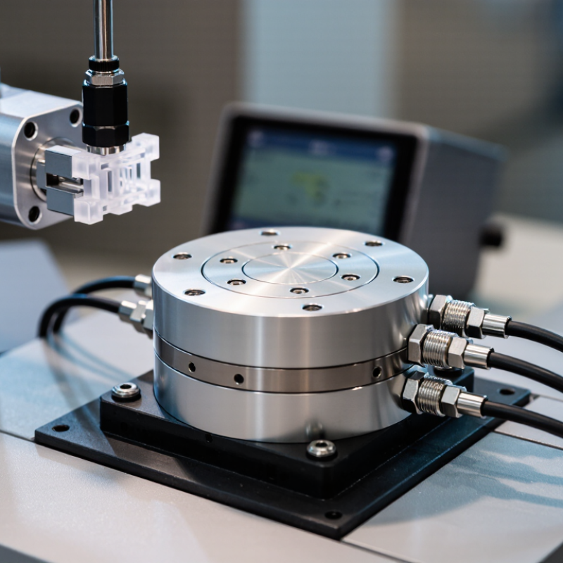
Define the Measurement Requirements and Operating Conditions
Before selecting a multi-axis load cell, list every force and moment component the test will produce. Record expected minimum, typical, and peak values for each axis. Include combined loading: a bracket may experience modest vertical force and substantial twisting at the same time. Set the required resolution and allowable error from the test objective, not from the sensor’s maximum capacity. Near the range limit, usable accuracy may suffer. Real fixtures are rarely perfect.
Next, describe the operating conditions. Note temperature changes, vibration, shock, humidity, cable movement, and how the cell will be mounted. These details affect zero stability and cross-axis response. State how quickly loads change, too; a slow press and a sharp impact need different bandwidths. NIST Technical Note 1297 explains uncertainty reporting and the use of expanded uncertainty, U = kuc. With k = 2, coverage is often approximately 95%, when the underlying assumptions are appropriate. Use this as a prompt to budget uncertainty across the sensor, amplifier, mounting, and calibration—not as a performance guarantee.
Finally, check overload risk and calibration needs for each axis and for combined loads. A cell rated for one axis may not tolerate the same margin on another. Document the fixture, load direction, and temperature used during calibration so test results can be repeated. This takes time. It is still easy to overlook cable forces or a slightly misaligned bolt pattern. Those small setup effects can distort the measurement before data collection even begins.
Identify the Required Axes and Load Directions
7 Tips for Choosing a Multi Axis Load Cell
Identify the Required Axes and Load Directions
Before selecting a multi axis load cell, list every force and moment your setup must measure. A three-axis model may capture forces along X, Y, and Z, while other models also measure moments around those axes. Do not assume every unit measures the same components. Check the datasheet and calibration certificate.
Map the sensor’s axes to your equipment. If a test bracket pushes sideways and downward, note both directions and their expected signs. Also record whether each load may reverse, such as tension becoming compression. This detail matters. A clear sketch with arrows can prevent a sensor from being installed at 90 degrees to the intended coordinate system.
Consider combined loads, not just one direction at a time. A fixture may apply vertical force while also producing a twisting moment. Confirm that the chosen sensor measures those components and can handle their expected ranges. Small tests help. Apply a known load along each axis and compare the readings with your sketch. If the results seem inconsistent, revisit the mounting orientation and sign convention before changing the setup. Even a tidy drawing can leave room for interpretation, so document the final axis definitions where technicians can see them.
7 Tips for Choosing a Multi Axis Load Cell: Identify the Required Axes and Load Directions
Illustrative load case: The example shows peak force components of +120 N on X, −80 N on Y, and +500 N on Z. The signs indicate direction in the chosen coordinate system. Identify which axes must be measured and check whether the sensor’s force and moment ranges suit the application; moment components are not shown here.
Match Capacity, Accuracy, and Sensitivity to the Application
Selecting a multi-axis load cell begins with the forces and moments the fixture will actually experience. Estimate each axis separately, including brief peaks caused by impact, acceleration, or tool contact. A sensor sized only for the largest force may still be overloaded on a moment axis. A margin is useful. But excessive capacity can make small changes harder to measure. Check the rated capacity and overload limits for every axis in the technical specifications.
Accuracy and sensitivity are related, but they are not interchangeable. Accuracy describes how close a reading is to the applied load; sensitivity describes how much the output changes as load changes. Review accuracy on each axis, and note whether it is specified as a percentage of full scale or of the reading. That difference matters at low loads. For a task involving small side forces, a highly sensitive channel may help, provided its noise and resolution suit the measurement system. Check cross-talk too: a strong force on one axis can influence another channel. Mounting matters. Misalignment or uneven contact can distort results, even with a well-specified sensor. In practice, test the assembled setup with known loads in several directions. I would not assume a catalog value tells the whole story; temperature, cabling, and fixture stiffness can change measurements. Keep those conditions consistent during calibration and use.
Assess Mounting, Materials, and Environmental Compatibility
A multi-axis load cell is only as reliable as its load path. Check the mounting face for flatness, align each axis with the applied force, and use the specified bolt torque. A tilted bracket can turn a vertical load into unwanted side force. Fit matters. For wet or salty sites, stainless steel can resist corrosion better than many alloy steels, but seals, fasteners, and cable entries also need protection. A strong sensor with a poorly sealed connector is still vulnerable.
Environmental limits deserve equal attention. OIML R 60:2017 specifies a minimum temperature span of 30 °C for load cells, so compare that requirement with real operating conditions, not just room temperature. Heat from a nearby motor, cold washdown water, or condensation can shift readings or damage electronics. Ask how temperature effects are specified for each axis, and confirm whether the calibration matches the installation. One imperfect point: a laboratory check may not capture vibration or uneven thermal gradients on your machine.
Tips: Sketch the mounting stack-up before ordering. Record expected load, shock, humidity, cleaning chemicals, and temperature extremes. Then test the assembled sensor under representative conditions; small misalignments often appear only after installation.
7 Tips for Choosing a Multi Axis Load Cell - Assess Mounting, Materials, and Environmental Compatibility
| Tip | Selection dimension | What to check | Practical guidance |
|---|---|---|---|
| 1 | Required force and moment ranges | Maximum and typical loads on each axis: Fx, Fy, Fz, Mx, My, and Mz. | Estimate peak loads, including acceleration, impact, and off-center loading. Choose ranges that cover expected peaks while retaining adequate resolution for normal measurements. |
| 2 | Mounting interface and load path | Bolt pattern, locating features, available space, cable exit, and the direction of applied loads. | Confirm that the sensor fits the fixture and that loads pass through its intended measurement axes. Use flat, stiff mating surfaces and follow the specified fastener and installation requirements. |
| 3 | Cross-talk and measurement accuracy | Rated output, nonlinearity, hysteresis, repeatability, and cross-talk between axes. | Compare specifications under the intended loading conditions. For applications measuring small forces on one axis while other axes carry larger loads, pay particular attention to cross-talk and calibration data. |
| 4 | Sensor material and surface finish | Sensing-body material, protective coating, and compatibility with moisture, cleaning agents, or process fluids. | Select materials and finishes suited to the actual chemical and cleaning exposure. Corrosion resistance depends on the specific medium, concentration, temperature, and exposure duration. |
| 5 | Temperature and thermal effects | Operating and storage temperature limits, temperature compensation, and temperature-related zero or sensitivity drift. | Check both ambient and sensor-body temperatures, including heat from nearby equipment. Allow the sensor and structure to reach a stable temperature when measurement accuracy requires it. |
| 6 | Ingress protection, vibration, and shock | Enclosure protection rating, cable and connector sealing, vibration exposure, and possible impact loads. | Match protection to the installation location; an enclosure rating does not automatically cover an unmated connector or cable joint. Check whether external vibration or shock could affect readings or exceed allowable loads. |
| 7 | Signal conditioning and calibration | Output type, excitation or supply requirements, channel count, connector pinout, calibration certificate, and data acquisition compatibility. | Verify that the controller can read all required channels and apply the sensor’s calibration matrix. Plan cable routing and grounding to reduce electrical noise, and confirm calibration coverage for the intended axes and load ranges. |
Review Calibration, Signal Output, and System Integration
A multi-axis load cell can read force and torque accurately on a bench, then drift after installation. Calibration should match the real load directions, mounting stiffness, and temperature range. ISO 376:2011 sets class 00 limits of 0.05% for repeatability and 0.06% for reproducibility in force-proving instruments. These figures are useful benchmarks, not guaranteed performance for every multi-axis assembly. NIST Special Publication 250-31 also emphasizes force calibration over defined ranges, with measurement uncertainty documented. Ask for calibration data across relevant axes, not just one neat axial test. Small cross-axis errors matter.
Check whether the signal is analog, digital, or a combination, then match it to the controller’s input range and sampling rate. A millivolt-per-volt output needs suitable excitation and noise control; long cables near motors can add visible jitter. Confirm whether the supplier reports cross-talk, zero balance, and temperature effects, and how those values were measured. Integration details count. Verify connector pinouts, grounding, software units, and overload limits before installation. A bench test with a known load in each direction can reveal swapped channels or sign conventions. One awkward detail: real mounting surfaces are rarely perfect. Recheck after tightening, and keep the raw readings for comparison.
Related Posts
-
Top 10 Multi Axis Force Sensors for Global Buyers?
-
Unlocking Precision: How Multi-Axis Load Cells Revolutionize Weight Measurement in Modern Technology
-
Top 10 Benefits of Using Multi Axis Load Cell in Industrial Applications?
-
Understanding the Science Behind Torque Load Cells: Applications and Innovations
-
Unlocking Industry Potential with Strain Gauge Load Cells at the 2025 China Import and Export Fair
-

How to Choose a Ring Load Cell in 2026?