| Application Definition |
Measured force components |
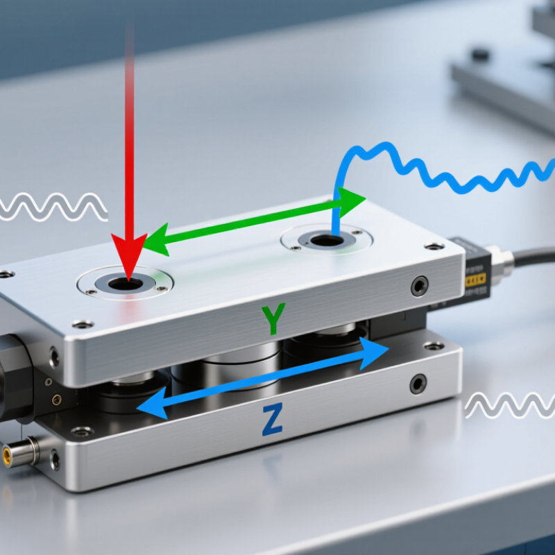
Three independent channels: Fx, Fy, and Fz. Select a sensor that matches the actual direction and combination of forces. |
List the maximum, minimum, static, dynamic, shock, and reversing loads expected in normal operation. |
Rated capacity should exceed the highest continuous working load while leaving sufficient margin for overloads and transients. |
Before selection and after major process changes |
| Capacity Selection |
Rated load and overload protection |
Choose separate capacity ratings for each axis where available. Avoid operating continuously near the rated limit. |
Compare the complete load envelope, including combined-axis loading and accidental impact loads, with the sensor specification. |
Normal operation remains within the manufacturer’s stated rated range; overload stops or mechanical protection are used where required. |
Design review and annual verification |
| Resolution |
Signal resolution and noise |
Resolution should be at least 5 to 10 times finer than the smallest force change that must be detected. |
Measure the zero output with the system unloaded and record peak-to-peak noise over a representative time period. |
Noise is small enough that the required measurement resolution is not obscured; filtering does not hide relevant transient events. |
Commissioning and quarterly monitoring |
| Combined Loading |
Cross-talk between axes |
Use the specified cross-axis sensitivity, commonly expressed as a percentage of the applied load or full scale. |
Apply a known force to one axis while measuring the output of the other two axes. Repeat for Fx, Fy, and Fz. |
Measured cross-talk is within the sensor specification and remains stable compared with the original calibration record. |
Initial calibration and after overload or mechanical impact |
| Mechanical Installation |
Mounting surface and alignment |
Use rigid, flat, clean mounting surfaces and the correct bolt grade, thread engagement, and tightening torque. |
Check surface flatness, remove burrs, align the sensing axes with the application coordinate system, and tighten fasteners in a controlled sequence. |
No visible rocking or gap; axis misalignment is within the application tolerance, typically no more than about 0.5° for precision work. |
Installation, relocation, and annual inspection |
| Load Introduction |
Force path and parasitic loads |
Loads should enter through the intended interface without unintended bending, torsion, cable pull, or side loading. |
Inspect adapters, brackets, bearings, and flexures. Confirm that cables are strain-relieved and cannot transmit force to the sensor. |
Force is applied through the designed load path; cable movement and fixture friction do not produce measurable output changes. |
Installation and whenever fixtures are changed |
| Environmental Suitability |
Temperature, moisture, and contamination |
Confirm the operating temperature range, temperature compensation, ingress protection, chemical compatibility, and cable rating. |
Install shielding, sealing, drainage, or environmental protection when exposed to washdown, dust, oil, condensation, or temperature cycling. |
The actual environment remains within the specified limits, and no moisture ingress, corrosion, or insulation deterioration is present. |
Continuous monitoring; visual inspection monthly or per risk level |
| Electrical Installation |
Excitation, grounding, and shielding |
Use the required excitation voltage or current, compatible input impedance, shielded cable, and suitable signal conditioning. |
Verify polarity, connector pinout, supply stability, grounding, cable routing, and separation from motors, relays, and high-current conductors. |
Supply remains within the specified tolerance; no unexpected zero drift, electrical interference, or intermittent channel dropout occurs. |
Commissioning and after electrical modifications |
| Warm-Up |
Thermal stabilization |
Allow the sensor and signal conditioner to reach a stable temperature before precision measurements. |
Power the system for approximately 15 to 30 minutes, or for the period established during validation, with no applied load. |
Zero readings stabilize within the project-defined limit before calibration or production measurement begins. |
At startup and after significant temperature changes |
| Zero Balance |
Unloaded output of Fx, Fy, and Fz |
Record zero values for all three channels at the normal operating temperature and fixture condition. |
Remove all external loads, wait for mechanical settling, and capture multiple zero readings rather than relying on one sample. |
Zero offset is within the sensor specification and does not show unexplained step changes or progressive drift. |
Before each critical test; daily for high-accuracy applications |
| Calibration |
Multi-axis calibration procedure |
Calibrate each axis independently and verify representative combined-load cases when the application uses simultaneous forces. |
Use traceable reference equipment with adequate capacity and accuracy. Apply increasing and decreasing loads at defined points and document the sequence. |
Indicated values meet the required accuracy, repeatability, hysteresis, and linearity limits for the application. |
At commissioning, typically every 6 to 12 months, or by risk-based interval |
| Reference Standards |
Traceability and uncertainty |
Reference loads should be traceable to a recognized national or international measurement standard. |
Maintain calibration certificates for reference instruments and include the measurement uncertainty in the calibration report. |
Calibration uncertainty is suitably lower than the allowable error of the 3-axis measurement system. |
Review at every calibration cycle |
| Data Acquisition |
Sampling rate and filtering |
Set the sampling rate high enough to capture the fastest event of interest; avoid excessive filtering that removes valid load changes. |
Validate sample rate, anti-alias filtering, digital filtering, channel synchronization, units, scaling, and time stamps. |
All three channels are synchronized and the recorded waveform represents the application’s relevant force dynamics. |
Commissioning and after software or hardware changes |
| Repeatability |
Repeated load response |
Use the same fixture, loading point, direction, and loading rate for repeatability checks. |
Apply the same known load several times and compare the indicated values after unloading and reloading. |
Variation is within the application tolerance and does not increase significantly over successive cycles. |
Monthly, quarterly, or according to process criticality |
| Hysteresis |
Increasing versus decreasing load output |
Evaluate the difference between readings taken at the same load during loading and unloading. |
Run a controlled loading cycle across the intended measurement range and compare corresponding points. |
Hysteresis remains within the stated sensor or project specification; sudden changes may indicate fixture friction or overload damage. |
During scheduled calibration |
| Long-Term Drift |
Zero and sensitivity stability |
Trend zero balance, span response, cross-talk, temperature, and calibration residuals over time. |
Use control charts or a digital maintenance log with the same reference load and test conditions whenever possible. |
Trend remains stable; investigate gradual drift, abrupt shifts, increasing noise, or channel-to-channel disagreement. |
Each verification cycle; review at least quarterly |
| Overload and Shock |
Post-event inspection |
Any overload, impact, dropped fixture, or unexpected machine collision should be treated as a potential calibration event. |
Inspect the structure and connectors, repeat zero and reference-load checks, and recalibrate if results have changed. |
No permanent deformation, cracked housing, damaged cable, unstable zero, or abnormal cross-talk is observed. |
Immediately after an overload or shock event |
| Maintenance Records |
Configuration and history |
Maintain sensor identification, installation orientation, capacity, wiring, calibration coefficients, test conditions, and service history. |
Store raw readings, environmental conditions, fixture details, operator, date, reference equipment, and corrective actions. |
Each result is traceable to a specific sensor, setup, software configuration, and reference standard. |
Every inspection, calibration, repair, or configuration change |
| Replacement Decision |
End-of-life indicators |
Consider replacement when performance cannot be restored through approved calibration, repair, or fixture correction. |
Compare current results with historical records and assess drift, noise, insulation, mechanical condition, and calibration uncertainty. |
Replace the sensor if it repeatedly fails acceptance limits, shows structural damage, suffers unstable output, or no longer meets measurement risk requirements. |
After failed verification and during annual asset review |

 sales@loadcellsensor.com