Leave Your Message
banner_21

Top Round Force Sensor Manufacturers and Suppliers

Choosing a Round Force Sensor supplier requires more than comparing catalog prices. The sensor must fit the load range, mounting space, and measurement conditions of the application. In a test fixture, for example, a few millimeters of clearance or an unexpected side load can affect installation and readings. Calibration options, overload limits, materials, and signal compatibility deserve close attention.

This guide to top round force sensor manufacturers and suppliers helps buyers compare capabilities without treating every product as interchangeable. It considers documented specifications, customization, technical support, and the availability of calibration information. Check whether performance data applies to the exact model you plan to use. Ask suppliers how they handle repeatability, environmental conditions, and integration questions. Small details matter. A clear datasheet is useful, but responsive engineering support can be just as important when a design changes. No shortlist is perfect, and supplier claims should be checked against project requirements. The right choice depends on the forces being measured, the system around the sensor, and the evidence available before purchase.
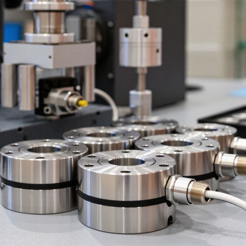
Top Round Force Sensor Manufacturers and Suppliers

Round Force Sensors: Compression Design, Load Paths, and mV/V Output

Round force sensors measure compression through a defined load path. Force enters the loading face, passes through the elastic body, and exits through the base. Strain gauges bonded to the body detect tiny deformations. A flat mounting surface and centered load help keep readings stable. Side loads can distort the result, even when the applied force seems small.

Output is commonly specified in mV/V, which normalizes the signal to the excitation voltage. For example, a sensor rated at 2 mV/V produces about 10 mV at full load with 5 V excitation. ISO 376:2011 specifies calibration at a minimum of eight force levels for force-proving instruments. That makes calibration points across the working range important, not just a check at rated capacity. A neat datasheet cannot correct a poor load path.

Tips: Keep contact faces clean and load the sensor axially. Check the mounting stack for gaps or uneven contact. Record excitation voltage during testing. A slightly imperfect setup can still produce a plausible reading, so verify alignment before trusting the number.

Key Specifications: Rated Capacity, 0.05% FS Accuracy, and Overload Limits

For top round force sensor manufacturers and suppliers, rated capacity should match the real load range, not just the largest expected force. A 5 kN sensor used mostly near 100 N may offer poor practical resolution, even when its datasheet looks impressive. Ask for usable measurement range, output at rated load, and calibration details. Small details matter.

ISO 376:2011 evaluates force-proving instruments through factors such as repeatability, reproducibility, interpolation error, and zero error. Its Class 00 criteria include a 0.05% relative repeatability limit, but that is not automatically equivalent to 0.05% of full-scale accuracy. Request the complete calibration certificate and confirm the stated accuracy basis, temperature range, and loading direction. Overload limits also need careful reading: safe overload, ultimate overload, and rated capacity are different values. A sensor surviving a brief overload may not retain its calibration. For example, a 2 kN unit with a stated 150% safe overload would tolerate 3 kN under specified conditions, not necessarily during repeated impacts. Specifications can be oddly optimistic. Check the test conditions before comparing suppliers.

Calibration and Traceability: ISO 376 and ASTM E4 Force-Verification Standards

Round force sensors can show different readings when mounting, load direction, or contact geometry changes. Calibration should therefore match the intended setup as closely as practical. ISO 376 classifies force-proving instruments by metrological performance, including repeatability, reproducibility, and reversibility. Its classes range from 00 to 2, with tighter limits at the higher-precision end. A calibration certificate should identify the applied force points, measurement uncertainty, and conditions. A certificate alone is not the whole story. Traceability depends on an unbroken calibration chain to recognized standards, with uncertainty documented at each step.

ASTM E4 sets a practical benchmark for verifying force-testing machines: indicated force should generally be within ±1% of the applied force over the verified range. This figure is useful, but it does not mean every round sensor is accurate to ±1% in every fixture. A sensor calibrated in compression may behave differently under eccentric loading or a small contact-area shift. Technicians should record orientation, preload, temperature, and loading sequence, then compare readings across repeated cycles. Small details matter. ISO 376 and ASTM E4 provide complementary evidence: one addresses force-proving instruments, while the other covers machine verification. The uncomfortable part is that traceability cannot correct poor installation; teams still need to question whether the test setup reflects real use.

Force Verification: ASTM E4 ±1% Error Limit

The bars show the maximum absolute indication deviation corresponding to a ±1% limit at selected force levels on a 100 kN range. Values are calculated from the stated force levels; they are not calibration results. ASTM E4 addresses verification of force-measuring systems, while ISO 376 classifies calibrated force-proving instruments. Their requirements are not interchangeable.

Round Force Sensor Manufacturers and Suppliers: Product and Service Comparisons

Round force sensors differ in more than diameter. Button-style models fit tight spaces, while annular designs allow a bolt or shaft to pass through the center. Buyers should compare rated capacity, overload tolerance, sensitivity, linearity, and temperature drift. A sensor that performs well on a bench may shift under side loading or repeated impact. Small details matter.

Grand View Research’s Force Sensor Market report estimated the global market at about US$2.4 billion in 2022 and forecast a 7.3% compound annual growth rate through 2030. This growth reflects wider use in automation, medical equipment, and industrial testing. For buyers, it makes supplier comparison more important, not less. Check whether quoted accuracy includes the signal conditioner, and ask for calibration data across the intended force range. A certificate alone may not show how the sensor behaves near its limits.

Service can separate similar products. Compare custom mounting options, cable lengths, sealing, connector choices, and delivery times. Ask whether calibration is traceable and whether the supplier can investigate drift after installation. Technical support matters. A lower price may exclude fixtures or integration advice, while a longer lead time can disrupt a test schedule. I would also request a sample under real loading conditions; specifications rarely capture every awkward fit.

Applications and Selection: Matching Sensor Capacity, Accuracy, and Environment

Top Round Force Sensor Manufacturers and Suppliers

Applications and Selection: Matching Sensor Capacity, Accuracy, and Environment

Round force sensors suit compact load paths, such as press platens, test fixtures, and robotic grippers. Choose capacity from the real force profile, not just the machine’s peak rating. A sensor used near its limit may overload during impact; one far above the working load may provide too little usable resolution. Check preload, side loading, mounting flatness, and whether the signal conditioner matches the sensor output. Small alignment errors matter.

Accuracy needs context. ISO 376:2011 groups force-proving instruments into four classes: 00, 0.5, 1, and 2. The standard concerns calibration performance, so its classes are useful reference points, not a guarantee of accuracy in every installed setup. Ask for calibration uncertainty, repeatability, hysteresis, and temperature effects across your operating range. A neat datasheet can still mislead. A sensor calibrated at room temperature may behave differently beside a warm press or in a damp washdown area.

Tips: Leave headroom for shock loads, and confirm the overload rating. For humid or dusty sites, check the enclosure protection rating and cable sealing. Test the complete assembly after installation; mounting surfaces and wiring can affect readings. Keep a record of zero drift and calibration dates. It is easy to overlook drift between checks.